solenoid unit has a manual override for emergency
operation.
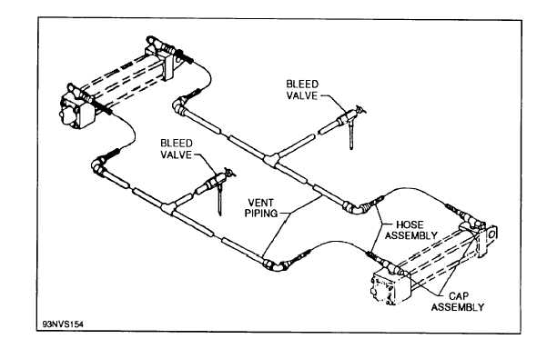
Emergency lowering bypass lines are connected
to the raising side of the hydraulic cylinder vent
piping assembly (fig. 5-8), and to the return lines of
the gravity tank.
The bypass lines permit fluid
passage around the four-way control valves and are
only used during an emergency situation to lower
the JBD panels.
Control System
The Mk 7 Mod 0 portable electrical system
control box (fig. 5-3) has six toggle switches. Three
of the toggle switches are used to raise or lower
individual pairs of JBD panel assemblies; the group
up-down toggle switch simultaneously raises or
lowers all of the panels in an installation; a power
on/interlock defeat toggle switch; and the cooling
water shutoff toggle switch closes or opens a remote
control shutoff valve located in the saltwater supply
line to the applicable JBD installation.
Lights are provided above and below the raise
(amber) and lower (green) switches to indicate the
JBD panel position.
A red light, near the
emergency cooling water shutoff switch, indicates a
malfunction in the cooling water system.
The umbilical cable connects to a receptacle on
the bottom of the control box and to a receptacle in
the flight deck. Wiring from the deck receptacle
goes to a junction box containing four terminal
boards; this junction box is the distribution point for
the portable electrical system and control box
circuitry.
A transfer switch is also provided for each JBD
installation so that in an emergency, electrical
control can be transferred from the portable control
box to the applicable auxiliary panel. This transfer
switch (fig. 5-9) is a rotary-type switch with a rotary
dial. The dial face is marked with two portable and
two auxiliary positions. When the transfer switch is
in the PORTABLE position, the portable electrical
control box is operational. Rotating the switch to
the AUX position will disconnect the portable
electrical control box and transfer operations to the
auxiliary control panel.
Preparation for Use
When the JBDs are put in operation for the first
time or after being idle, use the following
procedures:
1. Perform the preoperational inspection
according to
the applicable
maintenance
requirement card (MRC).
Figure 5-8.—Cylinder vent piping assembly.
5-7


