Central Charging Panel
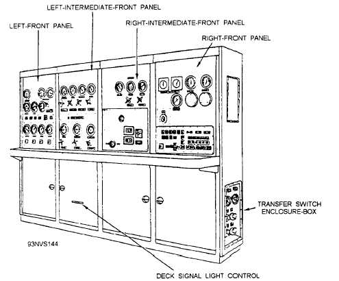
The central charging panel (fig. 4-82) is located
below decks in the retraction-engine compartment. The
panel consists of the left-front panel, left-intermediate-
front panel, right-intermediate-front panel, right-front
panel, transfer-switch panel, and launching-valve-
emergency-cutout-valve panel, which are described in
the following paragraphs. The deck-signal-light panel is
located inside the central charging panel, below the
left-intermediate front panel. Controls on the deck-
signal-light panel are used to adjust the intensity of the
deck signal lights. The panel enclosure also contains
pressure switches, gauge shutoff valves, and other
piping components.
LEFT-FRONT PANEL.— The left-front panel
controls and monitors the hydraulic system. The panel
contains pressure gauges and OFF-ON switches for the
main hydraulic pumps, the auxiliary pump, the
circulating pump, and the lubrication pump. Also
included are a gravity-tank fluid temperature gauge,
three accumulator hydraulic-pressure gauges, an
OFF-ON PUMP DELIVERY CONTROL switch,
RETRACTION-ENGINE SUSPEND switch, a blowd-
own valve for the retraction-engine hydraulic fluid, and
fuses.
LEFT-INTERMEDIATE-FRONT PANEL.—The
left-intermediate-front panel controls and monitors the
pneumatic system. Gauges on the panel indicate the air
pressure in the air side of the main hydraulic
accumulator, the air flask, the air side of the
cable-tensioner accumulator,
the low-pressure-air
supply, medium-pressure-air supply, and the air side of
the tensioner surge accumulator. A dual gauge indicates
the air pressure at the dome of the tensioner regulator
and the pressure in the hydraulic fluid side of the
tensioner surge accumulator. Valves on the panel are
used for charging and blowing down the air flask, the
air side of the main hydraulic accumulator, internal
tensioning accumulator, the air side of the cable-
tensioner accumulator, the dome of the tensioner
regulator, and the air side of the tensioner surge
accumulator. There is also a valve to shut off the
low-pressure-air supply. Lights on the panel indicate
pressure and temperature limits for various catapult
functions.
RIGHT-INTERMEDIATE-FRONT PANEL.—
The right-intermediate-front panel contains gauges for
monitoring the pressure of the two nose-gear-launch
accumulators. Two air valves on the panel are used for
charging and blowing down the nose-gear-launch-
manifold accumulator. The panel also contains the
4-62
Figure 4-82.— Central charging panel.