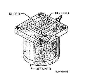
Figure 5-12.—Nose-gear-launch actuator reset assembly.
the slider provide for the flow of lubricant between
the slider and the inner walls of the housing. The
slider actuating spring is housed in a hole in the
bottom of the slider. The slider and spring are
secured in the housing by means of the retainer.
During operation when the slide assembly is
forward, the reset-assembly slider is not restrained
by the actuator assembly but is held above the
surface of the housing by the slider actuating spring.
After launch, as the slide assembly retracts, the
actuator-assembly
reset
tooth contacts
the
reset-assembly-slider pad surface, causing the
actuator assembly to rotate downward. This action
permits the buffer hook to drop below the deck
through the track opening into the deck housing
cavity (see diagram B, fig. 5-11). When the buffer
hook is below deck, the reset-assembly slider is held
down in the housing by the actuator assembly.
NOSE-GEAR-LAUNCH BUFFER CYLINDER
The NGL buffer cylinder (see fig. 5-13) is in the
deck housing between the NGL approach track and
the aft slide-access track. The buffer-cylinder body
has integral guide tracks on its top surface and
contains three hydraulic cylinders. The two outer
cylinders contain hollow piston rods; the center
cylinder piston rod is solid. The forward end of
each piston rod is attached to the NGL slide.
Within each outer rod is an orifice tube, which
meters fluid flow through the outer cylinders to
absorb the forward energy of the aircraft hookup;
the three piston rods are fully retracted into the
cylinders, and hydraulic fluid is constantly circulated
between the hydraulic system and the buffer
cylinder, bypassing the cylinders through two
metering orifice screws. This metered flow, which
is nonadjustable, prevents overheating of the
hydraulic fluid.
When the aircraft holdback bar engages the
buffer hook, the slide assembly moves forward,
pulling the three piston rods from the cylinders. As
the rods move forward, fluid in front of each
outer-cylinder piston is forced through the holes
around the periphery of each outer-cylinder piston
and through the metering holes in the two orifice
tubes. As the pistons continue forward, the number
Figure 5-13.—Nose-gear-launch buffer cylinder.
5-14