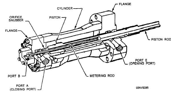
Figure 4-23.—Roto launching valve hydraulic cylinder.
when the crosshead has moved 3 1/2 inches. A second
actuated during the launching valve opening stroke to
limit switch stops clock No. 2 when the crosshead has
stop the two clocks that indicate the length of time
moved 9 inches through the launching valve opening
required for the crosshead (fig, 4-24) to move through
stroke. Deviations in the launching valve stroke can be
two predetermined distances. The clocks are started by
detected by comparing current timer readings with
a pressure switch; a limit switch stops clock No. 1
previously established timer readings.
4-20
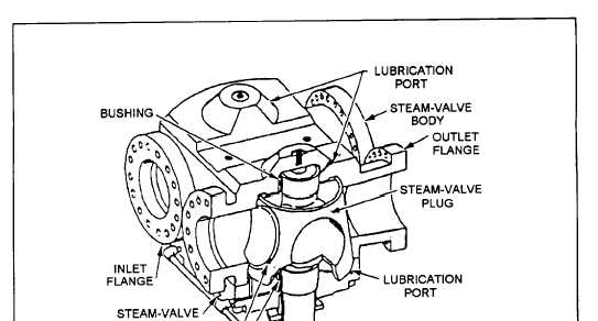
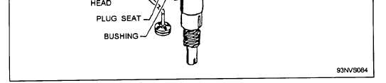
Figure 4-22.—Launching valve steam valve.