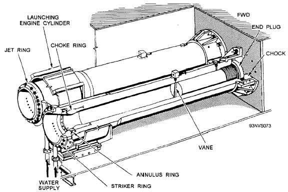
Figure 4-11.—Water-brake cylinder installation.
Water-Brake Tank
The water-brake tank is installed below the
water-brake cylinders to supply water to and reclaim
water spillage from the water brakes during operation.
It has a minimum capacity of 3,000 gallons of fresh
water. Overflow and oil-skimming funnels and bottom
drains are provided in the tank to maintain proper water
level and to remove excess oil used in the lubrication of
the internal components of the launching engine.
Water-Brake Pumps
Water is supplied to the water-brake cylinders by
two electric-motor-driven, rotary-vane-type pumps
installed in the immediate vicinity of the water-brake
tank. They are capable of producing 650 gallons of
water per minute at 100 psi. The pumps are electrically
interlocked so that if the running pump breaks down,
the alternate pump automatically starts running. Two
pressure gauges are installed, one per pump, to give a
visual indication of the pump discharge pressure.
Water-Brake Water Supply Piping
The suction inlets of the pumps are submerged in
the water-brake tanks. The pump discharges, each with
appropriate valves and a flow-limiting orifice plate, are
tied together and connected via flexible hoses to strainer
flanges at the bottom of the water supply pipes. Hoses
and rigid piping connect the pressure switches to the
supply pipes. A pump suction gauge and a pump
discharge gauge are located at each pump. These are in
addition to the gauges adjacent to the pressure switches.
The suction side of the pump consists of an inlet with
a foot (check) valve, a gauge valve, and a strainer
immediately ahead of the pump inlet. A petcock for
venting is mounted at the top of the strainer. The
discharge side of each pump includes an orifice, a
check valve, and a stop shutoff valve. Two discharge
lines merge into a single line, which later splits into
two lines. High-pressure, flexible hoses lead to and
connect to the brake cylinder water supply connectors,
which are attached to the water-brake cylinders. A drain
valve for the water-brake tank leads to an overboard
discharge. Fresh water from the ship’s system is added
to the tank via fill and shutoff valves in the water-brake
pump room.
Water-Brake Pressure-Sensing Switches
Two pressure switches are connected to the piping
leading from the pumps to the brake cylinders. (See fig.
4-1 2.) They usually are installed on the bulkhead
4-11