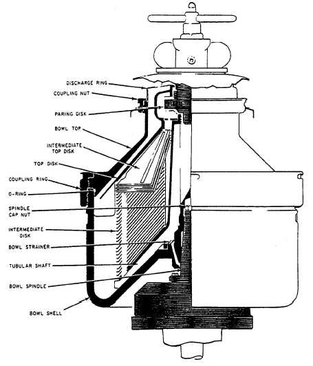
Figure 4-34.—Bowl shell assembly.
The bowl shell confines the liquids being
separated. Housed within the “tub-like” bowl shell are
the strainer, disk stack, paring and discharge ring.
The bowl shell has eight equally spaced drain
holes around the raised center of its bottom. These
holes facilitate draining the bowl when the purifier is
in its stopping cycle. The draining liquids are directed
into the annular space between the bowl shell and
the bowl casing and then out the bowl casing drain
line.
To ensure that the drain holes will not become
clogged by dirt from the bowl shell, a conical-shaped
strainer is installed over the top of the drain holes.
The bowl shell seats on the tapered portion of the
top of the spindle shaft. The threaded top section of
the spindle shaft protrudes up through the raised
center of the bowl shell. A spindle capnut is then
screwed down over the threads to force the bowl shell
down onto the tapered portion of the spindle shaft.
A slot is provided on each side of the bowl shell
on its outer surface near the top. These two slots
engage the bowl shell lock screws during disassembly
or assembly of the bowl shell. A notch at the
upper/outside edge of the bowl shell engages the bowl
top.
The tubular shaft is the base and the center of
the disk stack. It forms a circular bulkhead between
the feed inlet liquids and the disk-stack discharge to
the paring disk.
The base of the tubular shaft has three
unequally spaced pins that interlock with three
unequally spaced slots around the raised center of the
inside-bottom of the bowl shell. Thus, the tubular
shaft can be installed in one position only, ensuring
that the tubular shaft will rotate.
The flared base of the tubular shaft is the bottom
of the disk stack. A liquid passage. between the bowl
shell and the underside of the tubular shaft’s base, is
provided
4-39