FUEL-QUALITY MONITORS
Fuel-quality monitors (formerly called go/no-go
gages) are installed after filter/separators on truck fill
stands and on all equipment that directly fuel
aircraft. Monitors are not required for use with
product receipt filters or those used exclusively for
recirculation of fuel. A pressure gage is also installed
on each monitor housing so that the differential
pressure across the elements can be recorded. If the
filter/separator also incorporates fuel monitor
elements, the gage or gages are installed so that the
pressure losses across the filter elements and monitor
elements can be recorded separately.
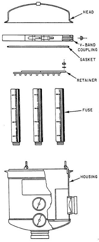
The fuel-quality monitor (fig. 7-2) provides a
continuous check on the cleanness of the fuel passing
through the filter/separator. Fuel that meets a
predetermined standard of cleanness passes through
the monitor with a minimum drop in pressure. Fuel
containing quantities of solids and/or water above the
predetermined acceptable level is automatically cut
off.
The fuel-quality monitor has an aluminum
housing and various numbers of fuses, depending on
the model. Each fuse of the monitor is a self-
contained unit consisting of specially treated paper
washers housed within a metallic housing and fitted
with plastic end fittings. The sensing washers,
housed within the metallic housing, absorb free or
suspended water from the fuel.
RELAXATION CHAMBERS
A relaxation chamber, consisting of a tank or
piping, follows the fuel monitor, or filter/separator if
no monitor is installed in the system. This chamber
allows static electric charges, which develop as the
fuel passes through the filtration equipment, to
“relax” before the fuel enters a tank. Since the fuel
must be in contact with the metal walls of the
relaxation device for at least 30 seconds, the exact
size of the relaxation tank, or length of piping, is
determined from the maximum flow rate of the
system. Only one relaxation chamber is needed for
each fuel monitor, filter/separator combination. Any
tank, chamber, or other arrangement used to meet
this requirement must assure complete product
turnover, have a water drain at its low point, and a
manual or automatic air eliminator.
Figure 7-2.—Fuel-quality monitor.
7-3