—If this appears to be the trouble, remove the
adjusting screw housing, loosen the jam nut, and
turn the adjusting screw clockwise until it bottoms.
This should close the pressure-relief control valve. If
this was the trouble, the pressure settings should be
re-adjusted as outlined in the operating instructions.
The fueling valve diaphragm may be ruptured.
This occurrence is very unlikely. However, if all other
steps have been followed and indications are that the
main valve is faulty, follow these steps:
1. Remove all fittings from the cover of the
fueling valve.
2. Remove the nuts holding the cover in place
and lift off the cover.
3. Lift the diaphragm assembly out of the valve
and examine the diaphragm for any holes.
4. Replace the diaphragm with a new one if
necessary.
5. While the diaphragm assembly is out of the
valve, the disk should be checked to see that it is in
good condition. Replace if necessary.
6. When reassembling the valve, make sure the
internal spring fits into its recess in the cover.
7. When the valve is returned to service, follow
the procedure outlined in the operating instructions.
HOSE REELS
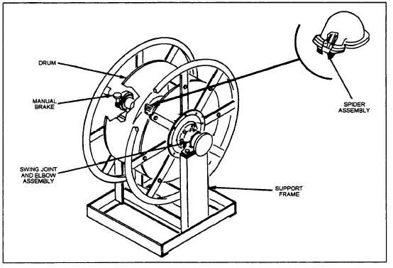
Each hose reel assembly (fig. 5-11) stores 150
feet of 2 1/2-inch collapsible hose or 1 1/2-inch non-
collapsible hose. Each hose reel assembly consists of a
drum, swing joint and elbow assembly, a support
frame, and a manual brake. The drum holds, reels,
and unreels the hose. The swing joint and elbow
assembly permits rotation around the central axis of
the drum, and also houses a spider assembly for the
continuity circuit. The support frame provides
permanent mounting for each drum. The manual
brake prevents the drum from rotating when not in
use.
The swing joint (fig. 5-12) is made of brass, to
resist corrosion. The continuity wire enters the top of
the flange on the fuel inlet side of the swing joint. It
is connected to an amphonel stud that is insulated
from the brass to prevent grounding out. Both ends of
the stud have very small O-rings that are held in
place by flat washers. The washers are, in turn, held
in place by nuts that are threaded on to the amphonel
stud.
Figure 5-11.—Hose reel assembly.
5-10