
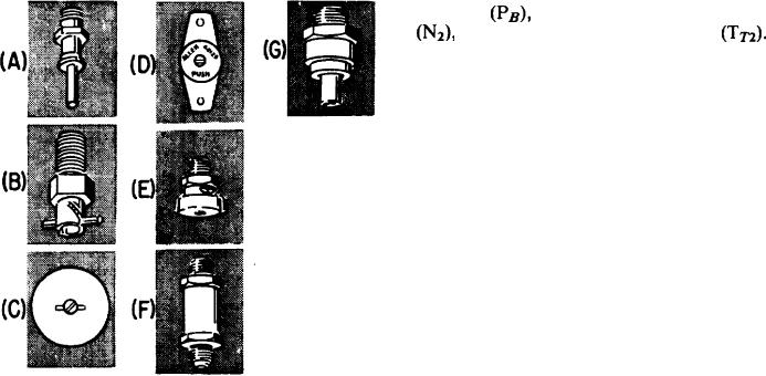
Figure 4-15, views A through G, shows seven
of the low-point drain. The valve is automatically
different types of fuel drain valves used on
actuated open at 1.0 psi minimum and closes at
aircraft.
3.0 psi maximum.
The valve shown in view G is usually found
The valve shown in view A is usually located
in the low-point drain, forward sump cell, and
in the boost pump or in the low-point drain. This
is opened by pushing and holding. It is closed by
fitting needs to be pushed up and held to have
releasing the plunger.
it in the OPEN position. To close the valve, you
should release the plunger.
The valve shown in view B is usually found
ENGINE FUEL SYSTEM
in the main fuel filter drain. To open this type
Fuel from the airframe fuel system is supplied
of drain, you should rotate the bar counterclock-
to the engine-driven fuel pump through the engine
wise to lock it in the OPEN position. To close the
fuel supply hose. The engine fuel supply hose is
drain, rotate the bar in the clockwise direction.
the last link between the airframe fuel system and
The valve shown in view C is usually located
the engine fuel system. Fuel from the engine-
in the inboard or outboard compartment low-
driven fuel pump is directed to the fuel control.
point drain. To open and lock it in the open
Then it is regulated and distributed to the
position, insert a screwdriver in the slot and turn
combustion chambers. Components of the engine
it clockwise (about 90). To close this valve, turn
fuel system are discussed in the following
the screwdriver counterclockwise.
paragraphs, along with operation.
The fuel drain valve shown in view D can be
FUEL CONTROL (JFC 25-3)
opened by inserting a screwdriver in the slot,
OPERATION
pushing in, and holding it, which will allow fuel
to flow. It can be closed by releasing the
The JFC 25-3 hydromechanical fuel control,
screwdriver.
shown in figure 4-16, is a lightweight, high-
The fuel drain shown in view E is for the aft
capacity, fuel-flow-metering unit. It is designed
boost pump drain. It can be opened and locked
to permit selection of a desired engine jet thrust
in the OPEN position by rotating it in the
level. It also provides automatic compensation
counterclockwise direction. Rotating it in the
through the full range of thrust for the ambient
clockwise direction will close the valve.
operating conditions encountered during flight.
Engine thrust during ground operation and under
The valve shown in view F is usually found
various flight conditions is controlled by a single
in the low-point drain and in the main vent line
power lever. It also regulates fuel for engine
starting and shutdown. The variables sensed by
the fuel control are power lever angle, burner
high-pressure compressor speed
pressure
and compressor inlet temperature
By
using these variables, the fuel control accurately
governs the engine's steady-state. It is selected
through a speed-governing system of the propor-
tional or droop type. The fuel control also uses
these same variables to control fuel flow for
acceleration and deceleration.
The fuel control consists of a fuel-metering
system and a computing system. The metering
system regulates fuel supplied to the engine by the
engine-driven fuel pump to provide the engine
thrust demanded by the pilot. Fuel regulation is
also controlled by engine operating limitations,
as sensed and scheduled by the fuel control
computing system. The computing system senses
and combines various operational parameters to
govern the output of the metering system of the
fuel control under all engine operating conditions.
High-pressure fuel is supplied to the control
inlet from the engine-driven pump. At the inlet
Figure 4-15.-Fuel drain valves.
4-20