
Either the upper or lower half is removed for
inspection or maintenance of the rotor and stator
blades.
The function of the vanes is twofold. They
receive air from the air inlet duct or from each
preceding stage of the compressor. It is delivered
to the next stage or to the burners at a workable
velocity and pressure. They also control the
direction of air to each rotor stage to get the
maximum compressor blade efficiency.
The rotor blades are in front of the inlet guide
vane assembly. The guide vanes impart a swirling
motion to the air entering the compressor in the
direction of engine rotation. This motion
Figure 1-19.-Bulb root-type rotor blades.
improves the aerodynamic characteristics of the
compressor by reducing the drag on the first-stage
rotor blades. The inlet guide vanes are curved and
airfoil shaped. The vanes are made of steel alloy,
many with a protective coating to prevent erosion.
They are welded to steel inner and outer shrouds.
The variable inlet-guide vanes are fitted and
pinned to spherical bearings that are retained in
the compressor front frame.
At the discharge end of the compressor, the
stator vanes straighten the airflow to cut
turbulence. These are straightening vanes or the
exit guide vanes.
The casings of axial-flow compressors support
the stator vanes and provide the outer wall of the
axial path the air follows. They also tap off
compressor air for various purposes, such as
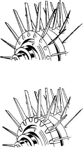
Figure 1-20.-Fir-tree root-type rotor blades.
cockpit pressurization and heating, or fuel tank
pressurization. There are outlet ports for bleeding
off compressor air at different stages, depending
or shroud without serious damage. This condition
on the pressure or temperature desired. (The
may occur if rotor blades become excessively loose
temperature rises proportionately with pressure
or by reduction of rotor support by a malfunc-
increase.)
tioning bearing. Even though blade profiles reduce
The stator vanes are made of steel with
such chances, occasionally a blade may break
corrosion- and erosion-resistant qualities. Fre-
under duress of rubbing and cause considerable
quently they are enclosed by a band of suitable
damage to compressor blades and stator vane
material to simplify the fastening problem. The
assemblies.
vanes are welded into the shrouds; then, the outer
shroud is secured to the compressor housing inner
The blades vary in length from entry to
wall by radial retaining screws.
discharge. The annular working space (drum to
The rotor blades are made of stainless or
casing) reduces progressively toward the rear by
semistainless steel. Methods of attaching the
the increase in the rotor drum diameter. The
blades in the rotor disc rims vary in different
rotor may feature either drum-type or disc-type
designs. They commonly fit into discs by either
construction.
bulb (fig. 1-19) or fir-tree (fig. 1-20) type roots.
The drum-type rotor is machined from a single
The blades then lock by grub screws, peening,
aluminum alloy forging. Dovetail grooves are
locking wires, pins, or keys.
machined around the circumference of the drum
Compressor blade tips reduce in thickness by
for blade retention. Provisions for bearing
cutouts, and are referred to as blade "profiles."
supports and splined drive shafts are on the front
These profiles allow rubbing, when rotor blades
and rear faces of the drum.
come into contact with the compressor housing
1-16

