
Internal tanks are pressurized anytime the
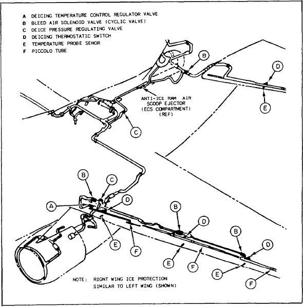
The anti-ice system shown in figure 6-17 is a
engine is running, provided that electrical power
combination of both deice and anti-ice systems,
is on, the refueling probe is retracted, the tad hook
and is called an ice protection system. Using bleed
is up, and weight is off the wheels.
air, temperature sensors, thermostatic switches,
Fuel transfer from external tanks to the
and various types of valves, ice protection
main airframe tanks using bleed air is also
requirements are met.
available, if the above conditions are met. During
emergencies, troubleshooting, or checking fuel
Airframes Fuel Systems
transfer after installing external tanks, an OVER-
RIDE switch is installed that defeats all conditions
The pressurization and vent system provides
except that the tailhook must be up.
regulated bleed air pressure to all fuel tanks. This
prevents fuel boil-off at altitude and provides a
AUXILIARY POWER UNITS
means to transfer fuel between tanks. This system
also provides pressure relief of the fuel tanks
Several types of aircraft now in the fleet
during ascent and vacuum relief of the tanks
have an onboard auxiliary power unit (APU).
during descent if the pressurization system fails.
Figure 6-17.-Ice protection system.
6-20

