
FLUID LINE IDENTIFICATION
Figure 9-4 shows a cutaway drawing, and
figure 9-5 shows an exploded view drawing.
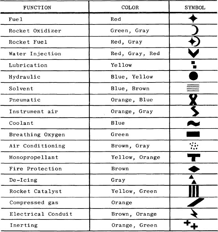
You can identify fluid lines in aircraft by
markers made up of color codes, words, and
Additional information concerning diagrams
geometric symbols. These markers identify each
is contained in the training manual Blueprint
line as to function, content, primary hazard, and
Reading and Sketching, NAVEDTRA 10077
direction of flow. Figure 9-6 lists the various types
(series).
Figure 9-6.-Fluid line color codes and symbols.
9-11

