
counter boards, one for each engine, The detector
each counter. The counters measure the period
receives a 0- to 33-volt, 0- to 70-hertz signal from
for their respective tachometer-generator signal.
Then, they compare the tachometer-generator
the voltage is cut to a constant 5 volts. The normal
signal period with the established clock reference
frequency signal is reshaped and processed
period. If the incoming generator signal period
through the counter circuit to establish a signal
is shorter than the clock reference period, the
period. The clock sets up a reference period for
counter energizes a switching relay. The relay
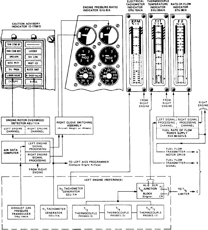
Figure 6-46.-F-14 engine instrument indicating group.

