
accelerometers. An azimuth gimbal lets the
Consider what happens to a stable element as
the aircraft flies over the surface of the earth. As
aircraft change heading without affecting the
the aircraft flies straight north from the equator
orientation of the stable element. A pitch gimbal
to the North Pole, the aircraft sees a continuing
removes the effect of aircraft pitch, and a roll
pitch maneuver. Look at figure 7-40, view A. At
gimbal stops the effects of roll. An extra roll
the pole, instead of the platform being level with
gimbal prevents the occurrence of gimbal lock
the surface of the earth, it is now 90 off level.
during certain aircraft maneuvers and makes the
system truly all-attitude. Look at figure 7-38. Note
GYRO TORQUING COMPUTATIONS. --
the inner roll gimbal that prevents gimbal lock,
To overcome the problems that arise from
which would cause the stable element to tumble.
platform tilt, the system uses the gyroscopic
Gimbal lock occurs when two of the gimbal axes
principle of precession. By using this principle as
become aligned parallel to each other. This causes
the aircraft flies over the rotating earth, it is
the stable element to lose one of its degrees of
freedom. When the aircraft exceeds 90 in pitch,
possible to apply a continuous torque to the
proper gyro axis. This reorients the gyros to
the outer roll gimbal rotates through 180. The
maintain the stable element horizontal to the
gimbals are oriented so the system may sense air-
earth's surface and pointed north. Figure 7-39,
craft attitude and heading by measuring angles
between the gimbals. Synchros send this informa-
tion to the attitude indicator and other systems
in the aircraft.
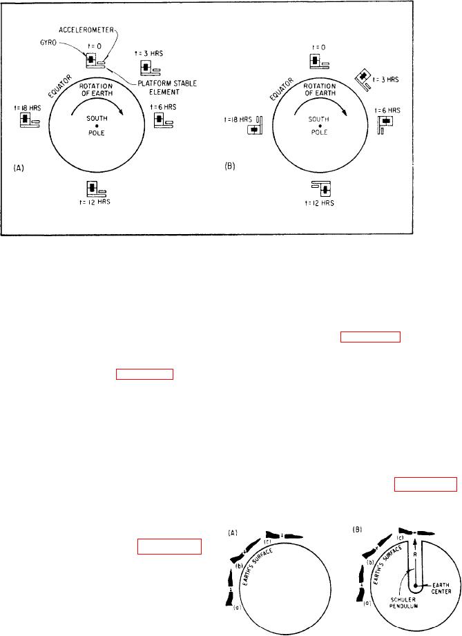
PLATFORM ORIENTATION. --Figure 7-39,
view A, shows the apparent rotation of a stabilized
platform located at the equator. As shown, the
platform will remain fixed with respect to
inertial space. However, it appears to rotate about
the surface of the earth as the earth spins about
its polar axis. This is undesirable for navigation
since the accelerometers will not remain horizontal
to the earth's surface. Consequently, this produces
gravitational components of acceleration in the
Figure 7-40.-Aircraft rate torquing: (A) without
torquing; (B) with gyro torquing.
outputs of the accelerometers.
7-31

