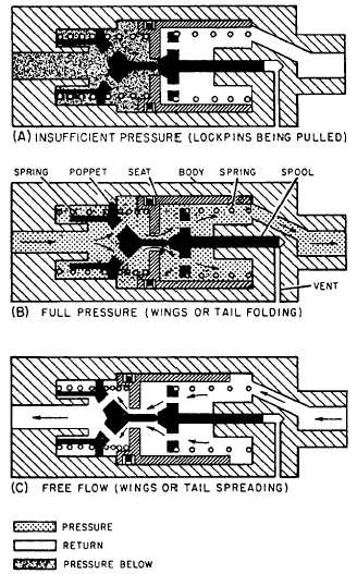
Pressure-Operated (Priority) Sequence Valve
The pressure-operated sequence valve, also called
a priority valve, looks like a check valve externally.
Like a check valve, the installation position is
indicated by an arrow. Figure 8-14 shows this valve
installed in a wing fold system.
During the wing folding cycle, pressure-operated
(priority) valves sequence the movement of the
lockpins and fold actuators. These valves ensure
lockpin actuation before fold actuator operation. This
completely automatic valve consists of a body
containing a spool, seat, poppet, related springs, seals,
and an end cap.
When the wing fold selector valve is in the fold
position, it directs fluid both to the wing lockpin and
to the pressure-operated sequence (priority) valve.
System pressure drops in the wing fold system
because of the amount of pressurized fluid needed to
actuate the lockpins. This lowers pressure below that
needed to open the pressure-operated (priority) valve.
View A of figure 8-14 shows insufficient pressure
to unseat the spool. When lockpins have completed
their travel, system pressure builds until it overcomes
spring tension and causes the poppet to unseat the
spool (view B of fig. 8-14). Fluid then flows freely
through the valve to the wing fold actuators.
View C of figure 8-14 shows the free-flow
position of the valve.
When spreading the wings,
return fluid moves the seat from the spool
compressing the poppet spring, which causes the
poppet to bottom and allows free flow of fluid
through the valve.
SHUTTLE VALVES
All aircraft incorporate emergency systems that
provide alternate methods of operating essential
systems required to land the aircraft safely. These
emergency systems usually provide pneumatic or
hydraulic operation of the essential systems; however,
in some cases due to the design, they maybe operated
satisfactorily through mechanical linkage. When
using the pneumatic or hydraulic emergency system,
that pressure must be directed to the unit concerned;
emergency pressure must not enter the normal
system, especially if the pneumatic type system is
used. To allow operating pressure to reach the
actuating unit and still not enter the other system, a
shuttle valve is installed in the working line to the
actuating unit. The main purpose of the shuttle valve
Figure 8-14.—View of priority valve.
is to isolate the normal system from the emergency
system.
Shuttle valves are located close to the actuating
unit concerned. This location reduces to a minimum
the units to be bled and isolates as much of the normal
system from the emergency system as possible. In
some installations, the shuttle valve is an integral part
of the actuating unit.
A typical shuttle valve is shown in figure 8-15.
The body contains three ports-the normal system
inlet port, the emergency system inlet port, and the
unit outlet port. A shuttle valve used to operate more
than one actuating cylinder may contain additional
unit outlet ports.
Enclosed in the body is a sliding part called the
shuttle. It is used to seal one of the two inlet ports. A
8-18


