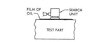
Figure 15-11.—Coupting of search unit to test part for transmission
of ultrasonic energy.
Ultrasonic Inspection
The term ultrasonic means vibrations or sound
waves whose frequencies are greater than those that
affect the human ear (greater than about 20,000 cycles
per second).
Ultrasonic inspection is a method of inspection that
uses these sound waves. The ultrasonic vibrations are
generated by applying high-frequency electrical pulses
to a transducer element contained within a search unit.
The transducer element transforms the electrical energy
into ultrasonic energy. The transducer element can also
receive ultrasonic energy and transform it into electrical
energy. Ultrasonic energy is transmitted between the
search unit and the test part through a coupling medium,
such as oil, as shown in figure 15-11, for the purpose of
excluding the air interface between the transducer and
the test part. The ultrasonic vibrations are transmitted
into and through the part. When the beam strikes the far
surface of the part or strikes the boundary of a defect,
the beam reflects back towards the transducer, travels
through the couplant, and enters the transducer, where
it is converted back into electrical energy. Then the
information is displayed on a cathode-ray tube (CRT,)
screen.
Ultrasonic inspections can be separated into two
basic categories-contact inspection and immersion
inspection. In the contact method, the search unit is
placed directly on the test part surface by using a thin
film of couplant, such as oil, to transmit sound into the
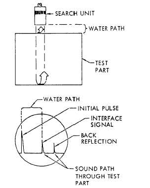
test part. In the immersion method, the test part is
immersed in a fluid, usually water, and the sound is
transmitted through the water to the test part
(fig. 15- 12). The immersion-type method is used to
inspect materials while they are immersed in a suitable
liquid, such as water or oil. This method proves more
satisfactory than contact testing for irregular-shaped
surfaces. Immersion inspection also permits use of a
wider range of testing frequencies. The three general
Figure 15-12.—Immersion method.
methods of contact inspections are straight-beam,
angle-beam, and the surface-wave method.
STRAIGHT BEAM.—The straight-beam method is
used to detect discontinuities parallel to the test surface,
and is generally used on material 1/2 inch thick or
greater. Most straight-beam methods are applied by
using the pulse-echo technique (transmitting and
receiving search unit or units placed on the same
surface). Certain applications use the through-
transmission method (transmitting search unit placed on
one surface, and receiving search unit placed on the
opposite surface). In the through-transmission method,
discontinuities block the passage of sound. This results
in a reduction of the received signal (fig. 15-13). With
this method, echoes from the discontinuities are not
shown on the CRT. Therefore, depth information on the
discontinuities is not determined. Typical discontinuity
examples are laminations, corrosion, and cracks.
ANGLE BEAM.—Angle-beam methods are used
extensively for field NDI, and can provide for inspection
of areas with complex geometry or limited access. This
is because angle beams can travel through a material by
bouncing from surface to surface. Useful inspection
information can be obtained at great distances from the
search unit. Angle-beam inspections are particularly
applicable to inspections around fastener holes,
15-10


