Figure 5-23.—Clamp installation.
assemblies are properly aligned and free of twists and
kinks. Complete tightening by using torque values
specified in applicable MIM. Table 5-9 is a guide for
installation torque of flared and flareless fittings.
Hold fitting stationary with one wrench, and use
torque wrench to tightens wivel nut. When applying
final torque, hold hose manually to prevent rotation
and scoring of the fitting’s sealing surface. Lockwire
the swivel nut (if applicable). Support flexible hose
or hose assemblies by routing and clamping hose or
hose assembly securely to avoid abrasion and kinking
where flexing occurs (fig. 5-22).
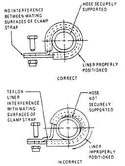
Overtightening clamps will squeeze or deform
hose. Cushion-type clamps should be used to prevent
hose chafing. See figure 5-23.
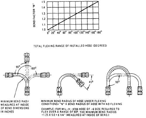
Make sure support clamps do not restrict hose
travel or subject hose or hose assembly to tension,
torsion, compression, or sheer-stress during flexing
cycles. Where flexing is required in an installation,
bend the hose in the same plane of movement to avoid
twisting. Ensure that the minimum bend radius is
greater by a factor of “N” than the minimum bend
radius for a nonflexing hose for hose assemblies
required to flex at a bend (fig. 5-24).
Figure 5-24.—"N" factor for flexing bends.
5-27