assembly consists of a bobweight, a viscous damper,
and a push-pull tube.
The push-pull tube is the
interconnect between the control stick and the
bobweight. The damper is located at the pivot point
of the bobweight and restricts fast movement of the
bobweight.
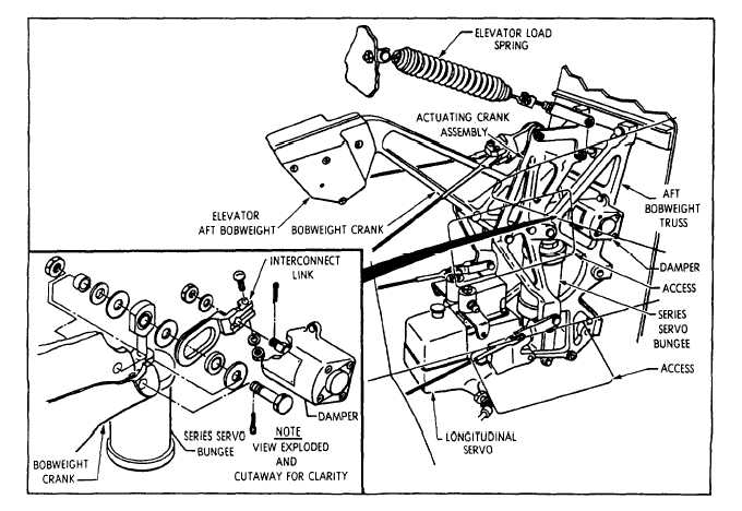
The aft bobweight and damper assembly works
with the forward assembly to overcome the heavy pull
of gravity and retard the chance of overcontrol. See
figure 9-4. This assembly is installed in the fuselage,
forward and below the horizontal stabilizer. It
connects to the elevator control cables.
The aft assembly consists of a bobweight, a
viscous damper, and a load spring. The bobweight
connects to the elevator control bell crank and the
damper. The load spring is between the elevator
control bell crank and the fin structure to balance the
forward and aft bobweights when the elevator is in a
neutral position.
The elevator power mechanism changes the
mechanical movement of the control stick to the
hydraulic operation of the elevator. See figure 9-5.
The mechanism is in the aft section of the aircraft
directly below the horizontal stabilizer. As in the
aileron power system, the mechanism consists of a
hydraulic power cylinder, control valves, linkage, and
hydraulic piping.
When the elevator controls are operated, the
control valves port hydraulic pressure to the power
cylinder. The hydraulic pressure extends or retracts
the cylinder piston to move the push-pull tubes. The
push-pull tubes deflect the elevators. The control
valves are two separate valves connected in tandem
by linkage. One valve is supplied hydraulic pressure
by the utility hydraulic system. The other valve is
supplied hydraulic pressure by the flight control
hydraulic system.
The power cylinder has dual
hydraulic chambers to work from each control valve.
Each hydraulic system simultaneously supplies
Figure 9-4.—Elevator aft bobweight and damper assembly.
9-4