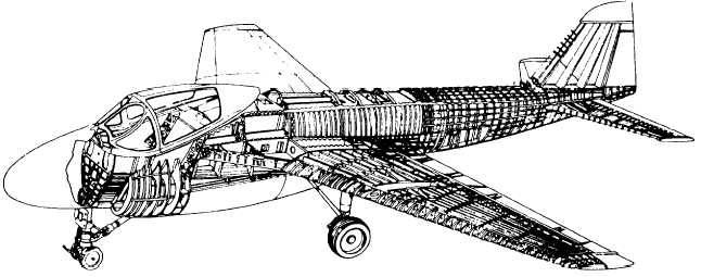
Figure 1-1.—Semimonocoque fuselage construction.
The semimonocoque fuselage is constructed
primarily of aluminum alloy; however, on newer aircraft
graphite epoxy composite material is often used. Steel
and titanium are found in areas subject to high
temperatures. Primary bending loads are absorbed by
the "longerons," which usually extend across several
points of support. The longerons are supplemented by
other longitudinal members, called “stringers.”
Stringers are lighter in weight and are used more
extensively than longerons. The vertical structural
members are referred to as “bulkheads, frames, and
formers.” These vertical members are grouped at
intervals to carry concentrated loads and at points where
fittings are used to attach other units, such as the wings,
engines, and stabilizers. Figure 1-1 shows a modified
form of the monocoque design used in combat aircraft.
The skin is attached to the longerons, bulkheads, and
other structural members and carries part of the load.
Skin thickness varies with the loads carried and the
stresses supported.
There are many advantages in the use of the
semimonocoque fuselage. The bulkheads, frames,
stringers, and longerons aid in the construction of a
streamlined fuselage. They also add to the strength and
rigidity of the structure. The main advantage of this
design is that it does not depend only on a few members
for strength and rigidity. All structural members aid in
the strength of the fuselage. This means that a
semimonocoque fuselage may withstand considerable
damage and still remain strong enough to hold together.
On fighters and other small aircraft, fuselages are
usually constructed in two or more sections. Larger
aircraft may be constructed in as many as six sections.
Various points on the fuselage are heated by station
number. Station 0 (zero) is usually located at or near the
nose of the aircraft. The other fuselage stations (FS) are
located at distances measured in inches aft of station 0.
A typical station diagram is shown in figure 1-2. On this
particular aircraft, station 0 is located 93.0 inches
forward of the nose.
Quick access to the accessories and other equipment
carried in the fuselage is through numerous doors,
inspection panels, wheel wells, and other openings.
Servicing diagrams showing the arrangement of
equipment and the location of access doors are supplied
by the manufacturer in the maintenance instruction
manuals and maintenance requirement cards for each
model or type of aircraft. Figure 1-3 shows the access
doors and inspection panels for a typical aircraft.
ENGINE MOUNTS
Engine mounts are designed to meet particular
conditions of installations, such as their location on the
aircraft; methods of attachment; and size, type, and
characteristics of the engine they are intended to
support. Although engine mounts vary widely in their
appearance and in the arrangement of their members,
the basic features of their construction are similar. hey
are usually constructed as a single unit that may be
detached quickly and easily from the remaining
structure. In many cases, they are removed as a complete
1-2