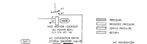
Figure 12-64.—AC generator drive system.
with approved metal closures. Repaired components
that are to be installed immediately subsequent to bench
testing should be drip-drained, capped, and plugged as
neccessary. Plastic plugs are prohibited because of the
possibility of plastic chips entering the component and
damaging seals or blocking critical passages.
The man-hours expended in correcting mal-
functions are documented on a VIDS/MAF. When apart
is removed and is to be processed through the IMA for
repairs, an additional VIDS/MAF is initiated with the
appropriate information tilled in and attached to the
component for turn-in. Consult the appropriate manuals
for proper documentation of the VIDS/MAF. The job is
not considered complete until the necessary paperwork
has been completed screened, and turned in.
GENERATOR DRIVE SYSTEM
(HYDRAULICALLY OPERATED)
The ac generator drive system shown in figure
12-64 is hydraulically operated by pressure from the
hydraulic power system. The AC GEN switch on the
copilot’s sub-instrument panel operates the shutoff
valve that controls the generator drive system. The
system consists of a shutoff valve, a hydraulically driven
motor a heat exchanger, a control switch, and a relay.
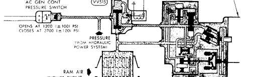
During normal aircraft operation and with the AC
GEN switch at OFF, the solenoid-operated shutoff valve
is energized (closed). The hydraulic motor lockout relay
is also energized. Under this condition, the generator
does not operate, since hydraulic pressure is stopped at
the shutoff valve. When the AC GEN switch is moved
to ON, the hydraulic motor lockout relay and the shutoff
valve is de-energized and the valve opens. Hydraulic
fluid at 3,000 psi is directed to operate the constant speed
variable displacement motor at 8,000 RPM. When the
fluid exits from the motor into the return lines, it is
routed through a heat exchanger and ram air cooled
before returning to the power system reservoir. When
ram air is not available on the deck, an electrically driven
blower is engaged automatically to provide airflow.
Maintenance of the generator drive system
normally consists of servicing, testing and checking for
proper operation, adjusting, troubleshooting, and
removal and installation of system components, flexible
line couplings, and other plumbing. Servicing and
maintenance procedures and precautions are listed in the
MIM and respective (03) overhaul manuals and must be
observed at all times to complete the procedures
efficiently and safely. Particular attention should be
12-74