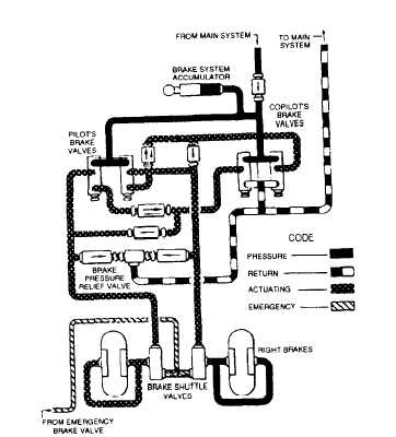
Figure 12-26.-Typical power brake control valve system.
When the brake pedals are released, the main
system pressure port in the master cylinder is closed off,
and fluid is forced out the return port, through the return
line to the brake reservoir. The brake reservoir is
connected to the main hydraulic system reservoir to
assure an adequate supply of fluid to operate the brakes.
When the emergency air system is used, air
pressure, directed through a separate set of lines, acts on
the shuttle valves, blocking off the hydraulic lines and
actuating the brakes.
POWER BRAKE CONTROL
VALVE SYSTEM
A power brake control valve system is used on
aircraft requiring a large volume of fluid to operate the
brakes. As a general rule, this applies to all patrol (VP)
and reconnaissance (VR) aircraft, and certain attack
(VA) aircraft. Because of the weight and size of the
aircraft, large wheels and brakes are required. Larger
brakes mean greater fluid displacement and higher
pressures. For this reason, independent master cylinder
type of systems are not practical on heavy aircraft. A
typical power brake control valve system is shown in
figure 12-26.
In this system, a line is tapped off from the main
hydraulic system pressure line. The first unit in this line
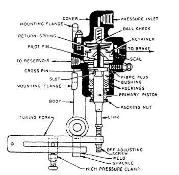
Figure 12-27.-Power brake control valve (pressure ball check
type).
is a check valve, which prevents loss of brake system
pressure in case of main system failure.
The next unit is the accumulator, the main purpose
of which is to store a reserve supply of fluid under
pressure. When the brakes are applied and pressure
drops in the accumulator, more fluid enters from the
main system and is trapped by the check valve. The
accumulator also acts as a surge chamber for excessive
loads imposed upon the brake hydraulic system.
Following the accumulator are the pilot’s and
copilot’s brake valves. The purpose of a brake valve is
to regulate and control the volume and pressure of the
fluid that actuates the brake.
Four check valves and two one-way restrictors,
sometimes referred to as orifice check valves, are
installed in the pilot’s and copilot’s brake actuating lines.
The check valves allow the flow of fluid in one direction
only. The orifice check valves allow unrestricted flow
of fluid in one direction, from the pilot’s brake valve;
flow in the opposite direction is restricted by an orifice
in the poppet. The purpose of the orifice check valves is
to help prevent chatter.
The next unit in the brake actuating lines is the
pressure relief valve. In this particular system, the
pressure relief valve is preset to open at 825 psi to
discharge fluid into the return line. The valve closes at
760 psi minimum.
Each brake actuating line incorporates a shuttle
valve for the purpose of isolating the emergency brake
12-32