and maintains a maximum of 9 to 11 psi in the
valve outlet chamber. Figure 1-4 illustrates the
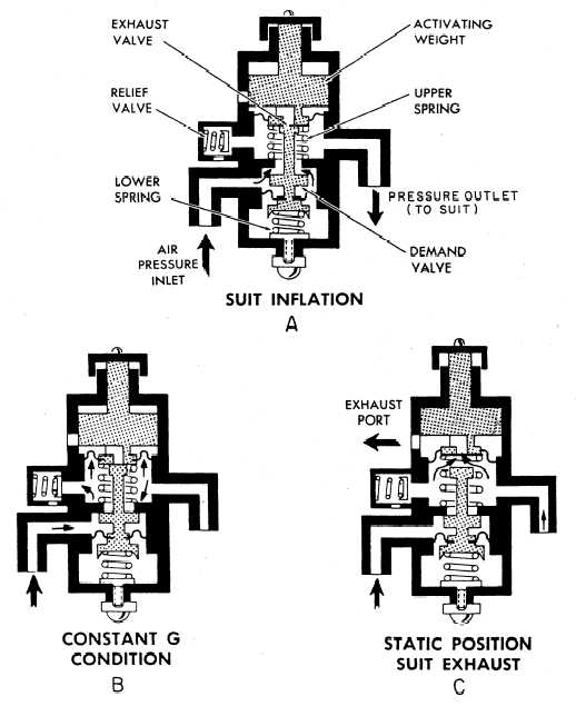
operation of the single-stage anti-g valve.
When a force of approximately 1.5 g’s is
exerted on the aircraft, the activating weight over-
comes the upper spring tension and closes the
exhaust valve (fig. 1-4, view A). As the weight
travels downward, it further depresses the valve
assembly, forcing the demand valve from its seat,
thus overriding the pressure of the lower spring
and opening the demand valve. Air pressure then
flows past the open demand valve, through the
valve outlet into the valve outlet line, through the
suit quick disconnect, and into the anti-g suit.
As the g forces being applied to the aircraft
are stabilized and become constant, the pressure
under the activating weight diaphragm builds up
sufficiently to lift the weight and to reduce the
pressure on the valve assembly enough to close
the demand valve (fig. 1-4, view B). The demand
valve closes under pressure of the heavier lower
spring, while the exhaust valve remains closed by
the activating weight. The suit pressure is then
trapped in the pressure outlet chamber of the
Figure 1-4.—Anti-g valve operation (single stage).
1-4