material as the original tubing or a suitable
substitute as specified in the MIM.
Valves
Various types of valves are installed in gaseous
oxygen systems. Among the most commonly
used are check valves, pressure-reducing valves,
and filler valves.
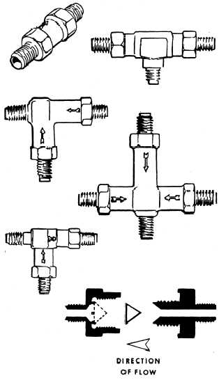
CHECK VALVES.— Check valves are in-
stalled at various points in the oxygen system.
Their purpose is to permit the flow of oxygen in
one direction only. Check valves are located in
the system to prevent the loss of the entire oxygen
supply in the event a cylinder or line is ruptured.
Various styles of single, dual, and triple check
valves are available, as shown in figure 4-3. The
arrow (or arrows) embossed on the valve casting
indicates the direction of flow through the valve.
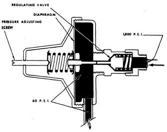
PRESSURE-REDUCING VALVES.— Pres-
sure-reducing valves (or pressure reducers) are
used in certain oxygen systems for the purpose
of reducing high cylinder pressure to a working
low pressure. In most installations the pressure
reducers are designed to reduce the pressure from
1,800 psi to a working pressure of 60 to 70 psi.
They are always located in the oxygen distribution
lines between the cylinders and the flight station
outlets. Figure 4-4 illustrates a typical pressure-
reducing valve.
FILLER VALVES.— A11 oxygen systems are
designed so the entire system can be serviced
(refilled) through a common filler valve. The filler
valve is generally located so it may be reached by
a man standing on the ground or wing. The filler
valve contains a check valve, which opens during
the filling operation and closes when filling is
completed. A dust cap keeps out dust, dirt, grease,
and moisture.
Gauges
Gauges are used in gaseous oxygen systems to
indicate the oxygen pressure in pounds per square
inch (psi). All systems are equipped with at least
one gauge that indicates the amount of oxygen
in the cylinder(s). The gauge also indicates
indirectly how much longer the oxygen will last.
Figure 4-3.—Oxygen system check valves.
Figure 4-4.—Pressure-reducing valve.
4-7