ram air, which is dependent on aircraft speed.
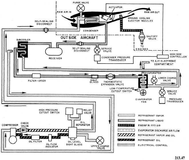
Figure 3-12 is a schematic diagram of the VEA6-1
vapor cycle ACS.
In the E-2 configuration, the vapor cycle
system cools, filters, and distributes avionics
compartment air at a temperature of 38°±5°F.
The system consists of a vapor cycle cooling
scoop assembly, an evaporator group assembly,
and air distribution ducting interconnected by
refrigerant lines and electrical wiring.
The evaporator assembly (fig. 3-13) is a
compact, quick-change package that can be easily
installed, removed, and serviced as a unit.
The assembly is composed of five quick-dis-
connect couplings; two shock mounts; tem-
perature controls; a hydraulic, motor-driven,
self-lubricating Freon compressor; a receiver; a
subcooler; a thermostatic expansion valve; an
evaporator; hydraulic motor-driven fan; and an
oil separator.
The vapor cycle cooling scoop assembly is
mounted on the top of the fuselage and consists
of a condenser assembly, ejector nozzles, an
actuator and flap, and a refrigerant pressure
actuator control switch.
The Freon 12 in the closed system is the
primary coolant. The forced air that is drawn
through the evaporator in a continuous cycle is
the secondary coolant. The electronic equipment
is cooled by the secondary coolant, which removes
heat by direct contact with the equipment to be
Figure 3-12.—Vapor cycle air-conditioning system.
3-18