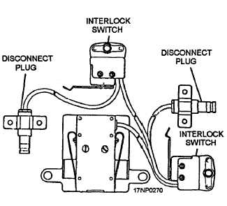
Figure 10-13.—Mk-39 electric fuze arming connector used on
the Aero 7A-5 bomb ejector rack.
Rotating the manual release nut mechanically actuates
the mechanical linkage. This raises the suspension hook
sears and opens the suspension hooks. The mechanical
linkage is also activated by the dual breech assembly.
The electrical junction box electrically connects the
bomb ejector rack to the aircraft’s weapons control
system. Electrical power is supplied from the aircraft
through the electrical junction box. This operates the
mechanical arming solenoids, the dual breech assembly,
and provides emergency operation of the rack. The
voltage required for electrical arming doesn’t pass
A1.
through the electrical junction box. A separate
connector assembly is located on the side of the bomb
ejector rack. It connects the Mk 39 electric fuze
connector to the aircraft’s fuze function control system.
The Aero 7A-5 has mechanical and electrical
arming capabilities. Two electromechanical solenoids
are attached to the bomb ejector rack. They give the
pilot the in-flight option of selecting nose only, tail only,
or nose and tail arming capabilities. When an armed
drop of an electrically fuzed weapon is desired, the
Mk 122 Mod 0 safety arming switch is installed in the
weapon. It is electrically connected to the Mk 39
electric fuze arming connector (fig. 10-13) during
weapon loading procedures. By using the Mk 122 Mod 0
safety arming switch, the weapon is free of the
suspension hooks before forwarding the fuze arming
signal to the electric fuze.
Aero 7B-4 Bomb Ejector Rack
The Aero 7B-4 bomb ejector rack (fig. 10-14) is
similar in operation to the Aero 7A-5 bomb ejector rack.
The Aero 7B-4 bomb ejector rack is 2 inches shorter in
height than the Aero 7A-5. This, together with
modifications in the aircraft keel, provides 4 inches of
additional deck clearance at the centerline fuselage
station on the A-6 aircraft. The side location of the dual
breech assembly and the rack mounting method also
differ from the Aero 7A-5.
REVIEW NUMBER 1 ANSWERS TO QUESTIONS Q1. THROUGH Q8.
To suspend stores weighing up to 2,000 pounds on the Aero 65A bomb rack, you
would use the Aero 1A adapter assembly.
A2.
Before you load a weapon on the Aero 65A bomb rack, you must cock and latch
the rack.
A3.
A4.
A5.
A6.
A7.
A8.
A 28-volt dc is required to energize the release unit of the Aero 65A bomb rack.
The MAU-38/A bomb rack is mounted on the bomb bays of the P-3 aircraft.
To connect a MAU-38/A bomb rack to a BRU-12/A bomb rack, you would use the
AAC 571 change.
The BRU-14/A bomb rack is a major modification of the Aero 65A bomb rack.
The BRU-14/A bomb rack is installed in the P-3C aircraft.
The BRU-15/A bomb rack is used on the wing stations of the P-3C aircraft.
10-10