contain a description of each gun component and an
explanation of how each component works. Figure 6-2
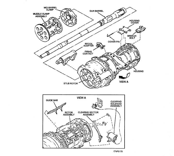
shows an exploded view of the gun components, and
figure 6-3 shows the gun component locations. As each
component is discussed, you should look at these
figures.
GUN COMPONENTS
The primary parts of the gun are described in the
following paragraphs.
Muzzle clamp assembly. The muzzle clamp
assembly is positioned at the outer end of the barrels. It
restrains individual barrel movement during firing. It is
positioned against the flange on the barrels and secured
by the pressure of the self-locking nut assembly against
the opposite side of the shoulders.
Mid-barrel clamp assembly. The mid-barrel
clamp assembly is positioned near the center of the
barrels. The clamp tabs are engaged in the slots of the
stop shoulders on the barrels. Secure the clamp in this
position by rotating the locating disk to the locked
position. The direction of rotation of the gun and barrel
hue prevents the clamp from unlocking. Insert a cotter
pin through the locking disk and clamp plate as an
additional safety measure.
Figure 6-2.—Gun components (exploded view).
6-2