The position depends on the aircraft and the
weapon/store requirements. For ease of removal and
installation, the ejector assembly is secured in the bomb
rack by a quick-release LOK pin assembly. The release
piston (fig. 10-18) is operated by gas pressure. It is used
to actuate the mechanical release linkage during
cartridge ejection, and to unlock the suspension hooks.
A properly installed safety pin assembly safes the
bomb ejector rack mechanically by blocking the
mechanical release linkage. Although the safety flag
assembly does not safe the rack electrically, it does
prevent ejection of loaded weapons/stores if the
cartridges are accidently fired. When the safety flag
assembly is inserted in the bomb rack, the safety pin
depresses the relief linkage assembly. The relief linkage
assembly then depresses one of the two breech relief
valves (fig. 10-17) to vent gases if a cartridge is
accidently fired.
The relief linkage assembly is
arranged so that one of the breech relief valves is
depressed regardless of which position the ejector
assembly is actually installed in the bomb rack.
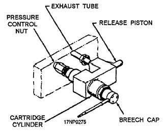
The BRU-10A/B bomb ejector rack has an auxiliary
release unit assembly. It provides an emergency method
of release if the ejector assembly or its electrical system
should fail. The BRU-10A/B bomb ejector rack
auxiliary release unit assembly (fig. 10-18) consists of
a pressure control nut, exhaust tube, release piston,
breech cap, and a breech cylinder. When the separation
cartridge is fired, the expanding gases supply the force
to actuate the release piston. The release piston extends
to actuate the mechanical release assembly, releasing the
suspension hooks. The suspension hooks release the
weapon/store. The auxiliary release unit assembly does
not eject the weapon/store. If a cartridge in the auxiliary
release unit assembly is accidentally fired, the installed
safety flag assembly prevents movement of the
mechanical release mechanism assembly. The gas
pressure generated by the ignition of the cartridge vents
to the atmosphere through an exhaust tube on the
auxiliary release unit assembly.
Organizational-level maintenance is limited to
cleaning, replacing, and corrosion control of damaged
parts and assemblies that can be replaced without
removal of the bomb rack from the aircraft. If a
BRU-10A/B bomb ejector rack requires inspection or
repair beyond the scope of the organizational
maintenance level, route the bomb rack to the
intermediate or depot maintenance level. A few of the
routine maintenance requirements are discussed in the
following paragraphs.
After every five firings or at the end of the day’s
operation, whichever occurs first, the ejector assembly
must be removed from the bomb ejector rack for
cleaning and inspection.
The actual cleaning and
inspection requirements are the same as for the bomb
ejector racks previously discussed. After the ejector
assembly has been disassembled, cleaned, and
inspected, you should lubricate the parts with a thin coat
of MIL-L-19701 lubricant prior to reassembly.
BRU-11A/A Bomb Ejector Rack
The BRU-11A/A bomb ejector rack is a
modification of the BRU-10A/B bomb ejector rack.
The BRU-11A/A is used on the wing stations of the S-3
aircraft. However, it doesn’t operate in exactly the same
way. The major difference between the two bomb
ejector racks is that the BRU-11A/A is equipped with an
IFOBRL. This mechanism consists of a remote-
controlled bomb rack lock and a remote-controlled
emergency release for the bomb rack lock. This allows
the bomb rack to be locked by the use of a
remote-controlled actuator during loading and during
flight. This eliminates the need for the safety pin
assembly used on the BRU-10A/B.
There are several different models of the
BRU-10A/B and the BRU-11A/A bomb ejector racks
currently in use. Part numbers are assigned to identify
the various models of configured bomb racks and are
used during maintenance.
Figure 10-18.—BRU-10A/B bomb ejector rack auxiliary
release unit assembly.
If you need more information about the
BRU-10A/B and the BRU-11A/A bomb ejector racks,
refer to Bomb Ejector Rack BRU-11A/A, NAVAIR
11-10C-24.
10-14