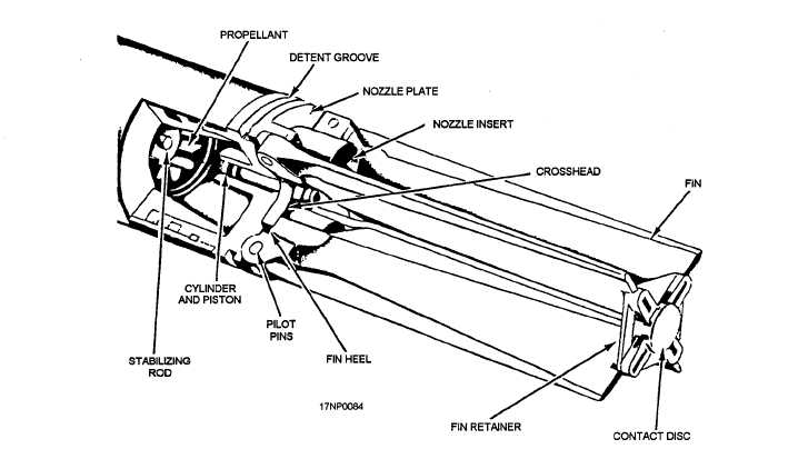
Figure 2-7.—Nozzle and fin assembly (2.75-inch).
NOZZLE AND FIN ASSEMBLIES.— The nozzle
and fin assembly (fig. 2-7) used with the Mk 4 and
Mk 40 motors consists of a nozzle plate, four nozzle
inserts, a fin-actuating mechanism, four fins, and a fin
retainer contact disc. The nozzle assembly for the
Mk 66 consists of the nozzle body, carbon insert, fins,
contact band assembly, and weather seal.
The fins are attached by pivot pins to lugs machined
on the aft part of the nozzle plate. When folded, the fins
lie within the 2.75-inch diameter of the rocket. The fins
are notched at the tips to allow attachment of a fin retainer.
The fin-actuating mechanism is a steel cylinder and
a piston with a crosshead attached to its aft end. When
the rocket is fired, gas pressure from the motor operates
the piston, cylinder, and crosshead. The crosshead is
pushed against the heels of the fins, causing the fins to
rotate on the fin pivot pins to the open position after the
rocket leaves the launcher. After the fins have opened
to the final flight position, the crosshead prevents the
fins from closing.
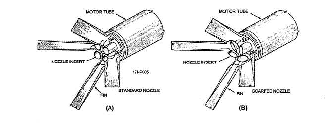
There are four nozzle inserts and the detent groove
in the aft end of the nozzle plate. They hold the rocket
in position after it is loaded in the launcher (fig. 2-8).
The major difference between the nozzle and fin
assemblies used on the Mk 4 and Mk 40 motors is the
type of nozzle inserts used.
Figure 2-8.—Nozzle and fin assemblies. (A) Mk 4 Mods motor (B) Mk 40 Mods motor.
2-6


