7.
8.
9.
10.
11.
12.
13.
14.
15.
16.
17.
SQ control knob–Controls the amount of
squelch threshold voltage in VO and AME
operations.
SQ OFF switch–When this switch is pressed,
the squelch circuits are disabled.
CPLR READY indicator–This indicator will
illuminate when the associated coupler is
properly tuned.
CPLR FAULT indicator–This indicator will
illuminate to indicate improper tuning of the
associated coupler.
SYS READY indicator–This indicator will
illuminate when the radio set has passed the
self-test routine.
SYS FAULT indicator–This indicator will
illuminate anytime the radio set fails self-test.
RESET switch–This switch resets the SYS
FAULT indicator to a GO condition after a
NO-GO condition was detected
XMTR OFF indicator–When this indicator is
illuminated the radio set cannot be used to
transmit. This indicator will come on during the
3-minute warmup period (the first 3 minutes of
initial power up), and anytime the operating
frequency is changed by more than 1 MHz.
Other than that, anytime there is a fault in the
system that affects the transmitter, this
indicator will illuminate.
VOL control–This control knob is not used in
the P-3 aircraft configuration.
BLANKER ON switch–This switch is not used
in the P-3 aircraft configuration.
COND switch–This switch selects the radio
set’s condition of operation.
a. OFF–This position removes primary power
from the radio set.
b. STBY–Applies power to the radio set’s RF
Amp final stage filament, frequency
standard and other critical circuits.
c. HI–Energizes the radio set and sets the
transmitter for high-power output.
d. LO–Energizes the radio set and sets the
transmitter for low-power output.
e. TEST–Initializes the radio set’s self-test
18. MODE switch–This switch selects the radio
set’s mode of operation.
a.
b.
c.
d.
VO–This position permits forced mode
selection by the COMM system selector
panel.
AME–This position permits AME
transmission and reception.
CW–With the switch in this position, the
radio set will transmit and receive
continuous-wave signals.
DATA, DIV, LSB–In this position, permits
forced mode selection by the COMM system
selector panel.
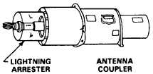
CU-2070/ARC Coupler
The CU-2070/ARC coupler (fig. 1-12) provides
impedance matching between the receiver transmitter
and the antenna. The lightning arrester provides a spark
gap to protect the radio if lightning strikes the long-wire
antenna.
Long-wire Antenna
There are two antennas used in the P-3 aircraft for
the HF system. Both are located external of the aircraft,
and stretch from the top of the vertical stabilizer to the
fuselage. The one on the left is used by HF-1, and the
one on the right is for the HF-2 radio set. Both of the top
mounts for the antennas are the breakaway type. If either
antenna breaks in flight, the wire will depart the aircraft.
This is designed for safety reasons. Should the wire get
hung up and not depart the aircraft, structural damage
could occur from the wire whipping against the
fuselage.
TSEC/KY-75 Security Unit
The TSEC/KY-75 provides the encoding and
decoding of the signals when the radio set is in the cipher
mode.
functions.
1-18
Figure 1-12.-CU-2070/ARC coupler.