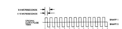
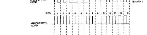
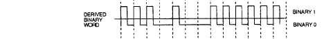
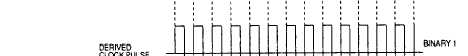
Figure 1-5.-Manchester decoding.
Because this makes both inputs to the second AND gate
to be 1’s, the output of the second AND gate will be 1.
This 1 will cause the integrator to charge, producing a
Manchester word bit of 1 during the second half of the
clock pulse. This type of bit is generated for timing
purposes only.
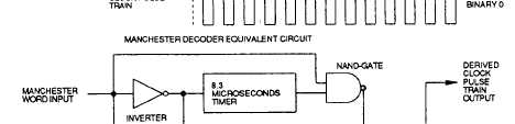
Manchester Word Decoding
When component receives a Manchester word, the
digital control circuits must decode the word into the
basic binary word and the clock pulse train. This process
is required prior to any further processing of the signal
by the component. A Manchester decoder equivalent
circuit and its input and output signals are shown in
figure 1-5.
The first input bit of the Manchester is always a 1.
This produces a 0 at the output of the inverter and the
inputs of the two timers. The same Manchester input bit
is applied to one input of the NAND gate. The 0 output
of the 8.3 timer is applied to the other input of the NAND
gate, giving an output of 1 from the NAND gate. This 1
is applied to the OR gate, making its output a 1. The 1
from the OR gate represents the first derived clock pulse
bit. This 1 is also applied to one of the inputs of the AND
gate. The other input is the original 1 from the
Manchester word. With both inputs to the AND gate
being 1, the output will be a 1. This 1 represents the first
bit of the derived basic data bit.
When the Manchester bit goes to 0, the inverter
output goes to 1 and starts the two timers. If the next
Manchester bit is 1, the two timers are restarted before
1-7