Figure 3-16.-SA-176/A RF transmission line switch.
processes valid IFF interrogations and provides coded
pulse train replies to give automatic radar
identification of the aircraft in one of five modes. The
five modes are discussed later in this chapter.
The transponder set also provides the Selective
Identification Feature (SIF) to permit a specific
aircraft to be selected from other properly responding
aircraft.
Major Components
The transponder set consists of four main boxes
and a test set. These components will be discussed in
the following text.
RF TRANSMISSION LINE SWITCH
SA-1769/A.— The RF transmission switch (fig. 3-16)
alternately connects the transponder set to the top or
bottom UHF L-band antenna. This switching (lobing)
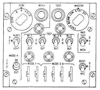
Figure 3-17.-C-6280(P)/APX transponder control box.
operates at 38 Hz. The lobing action prevents the
antenna system from being blanked out during aircraft
maneuvers.
TRANSPONDER SET CONTROL C-6280(P)/
APX.— The IFF control box (fig. 3-17) provides the
IFF transponder operational and test controls. The
IFF transponder control box controls the transponder
in any of the five modes: modes 1, 2, 3A, C, and 4.
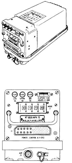
RECEIVER-TRANSMITTER RT-859/
APX-72.— The receiver-transmitter (fig. 3-18) will
Figure 3-18.-RT-859/APX-72 receiver-transmitter.
3-16