
Bow Thruster Control System
long and 2.3 feet wide. The rudder blades allow the
operator to maneuver the craft by deflecting the
The purpose of the bow thruster control system is
propeller slipstream at various angles.
to allow the operator to turn the bow of the craft and to
RUDDER CHANNEL SELECTOR SWITCH.--
move the craft in close places. This system is extremely
The rudder charnel selector switch is located on the
useful when the operator must dock and undock the
command and control (C&C) keyboard at the engineer
LCAC in the dry well of the support ship.
station. This switch, labeled RUDDER A/B, allows the
The bow thruster control system and assembly
operator to choose between channels of the CSEP in
c o n s i s t s of two bow thrusters (one port and one
case of an emergency or system fault.
s t a r b o a r d ) , the steering yoke assembly, and the
RUDDER CONTROL SYSTEM INDICA-
associated electrical and hydraulic operating
T O R S . Indicators are provided on the alarm and
m e c h a n i s m . The physical arrangement of these
monitor system (AMS) cathode ray tube (CRT) display
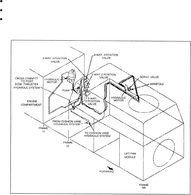
components and assemblies is shown in figure 7-6. The
monitor. The display monitor is located at the engineer
bow thrusters provide thrust for the craft. The controls
control station. The indicators include the following:
and operating mechanisms allow the control station
operator to control the rotation of the bow thrusters to
Rudder control failure
achieve the desired directional thrust. Basically, the
Port and starboard hydraulic reservoir low
control station operator uses the steering yoke in the
steering control assembly to turn the craff right or left,
Port and starboard hydraulic pressure low
respectively. Turning the yoke left causes the craft to
turn left, while turning the yoke right causes the craft to
turn right. The steering yoke contains potentiometers
Figure 7-6.--Physical arrangement of the LCAC bow thruster control system.
7-5