
The following simple setup procedural
steps should help you understand and calibrate
pressure transducers commonly found on gas
turbine ships. These steps are condensed from
paragraphs 8.2-24 and 8.2-25 of the Propulsion
Gas Turbine Module LM2500, Volume 2, Part 3,
NAVSEA S9234-AD-MMO-050.
To calibrate a 0- to 250-psig transducer, close
the instrumentation valve and remove the cap.
Remove the cover from the transducer and
connect the multimeter. The multimeter should
read 4 mA 0.3. If necessary, adjust the ZERO
ADJUST potentiometer. Now connect the
pressure hose to the instrumentation valve and
apply 250 psig to the transducer. The multimeter
should read 20 mA 0.3. If necessary, adjust the
SPAN ADJUST potentiometer to obtain this
reading. Recheck first and last values whenever
you make either ZERO or SPAN adjustments.
Now check the middle value, in this case 125 psi,
and the multimeter should read 12 mA 0.3. To
derive the middle value of the output current,
subtract 4 from 20, divide by 2, and add 4 to
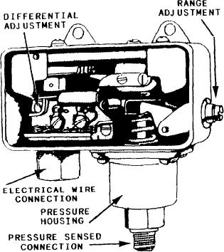
Figure 5-21.--Pressure switch.
the sum. For information on calibration of
transducers, refer to the Propulsion Gas
Turbine Module LM2500, Volume 2, Part 3,
electrical signal. Pressure switches are used
NAVSEA S9234-AD-MMO-050, or Pressure
to sense gauge or differential pressures on
Transducer - Strain Gauge Assembly, NAV-
pneumatic as well as hydraulic systems. They are
manufactured in many sizes and configurations,
SEA 0987-LP-059-5010.
but all perform basically the same function.
NOTE: When calibrating a differential
pressure transducer, apply the pressure to
Construction of Pressure Switches
the high port and vent the low port to the
atmosphere.
One of the simplest pressure switches is the
single-pole, single-throw, quick-acting one, also
PRESSURE SWITCHES
shown in figure 5-21. This switch contains a
seamless metallic bellows in the housing, which
Another type of pressure indicating instrument
is the contact or pressure switch. This instrument
is displaced by changes in pressure. The bellows
either opens or closes a set of contacts at a preset
works against an adjustable spring that determines
pressure. This switch can provide you with an
the pressure needed to actuate the switch.
alarm indication or initiate an action such as
Through suitable linkages, the spring causes the
stopping a piece of equipment at a preset pressure.
contacts to open or close the electrical circuit. This
Often when a measured pressure reaches a
is done automatically when the operating pressure
certain maximum or minimum value, a pressure
falls or rises from a specified value. A permanent
magnet in the switch mechanism provides a
sensing device activates. This may be in the form
positive snap on both the opening and the
of an alarm to sound a warning or a light to give
a signal. The pressure switch shown in figure 5-21
closing of the contacts. This snap action prevents
is a device commonly used to energize or
excessive arcing of the contacts. The switch is
de-energize an auxiliary control system. This
constantly energized. However, it is the closing
switch is normally contained in a metal case with
of the contacts that energizes the entire electrical
a removable cover. It is equipped with a pressure
circuit.
You can find switches in many sizes and
port and an electrical connector. The pressure
configurations. The switch used depends upon its
switch converts, through a set of contacts, the
application.
motion of a diaphragm or bellows into an
5-16

