
lower-frequency power turbine or the higher-
current enters the detector and is stepped up
by a transformer. This ac is then rectified to
pulsating dc, which is fed to the UV sensor.
ULTRAVIOLET FLAME DETECTOR
Ultraviolet light containing wavelengths in the
range of 1900 to 2100 angstrom units ionize the
Ultraviolet flame detectors are used in GTMs
gas in the tube. This allows the current to flow
to detect the presence of fire. These sensors are
through the tube. The current then goes to a pulse
used along with temperature sensors in the
transformer which couples it to the signal
LM2500. They are used alone in the Allison
conditioner.
501-K17 for fire protection. The fire detection
system alerts the operator of fire in the module.
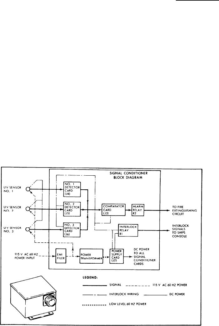
Flame-Detector Signal Conditioner
On twin-shaft ships it also activates the fire stop
sequence and releases fire-extinguishing agents to
The flame-detector signal conditioner (fig.
extinguish a fire in the Allison 501-K17 module
5-35) is contained in a metal box. The box is
or in the LM2500 module.
attached to the underside of the base/enclosure
of the LM2500. On the Allison 501-K17, the unit
Flame Detector
is located in the alarm terminal box on the
generator end of the module base.
The flame detector (fig. 5-34) is an electronic
Identical detector cards (one for each UV
tube that responds to UV radiation in ordinary
sensor) are located in the signal conditioner. The
flames. It is insensitive to infrared (IR) and
detector card amplifies, rectifies, and filters the
ordinary visible light sources. The tube has two
current pulses from the UV sensor. This provides
symmetrical electrodes within the gas-filled
an output voltage level proportional to the UV
envelope. It operates on pulsating dc. Alternating
light level at the UV sensor.
Figure 5-35.--Flame-detector signal conditioner block diagram and typical signal conditioner unit.
5-25

