
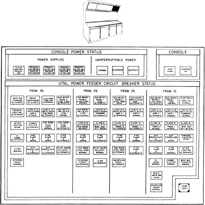
Figure 8-15.--CONSOLE POWER STATUS/CONSOLE/VITAL POWER FEEDER CIRCUIT BREAKER STATUS panel
(A-3).
right panel (fig. 8-15). It has the console power
POWER SUPPLIES.--This subsection has
status, console, and vital power feeder circuit
the indicators that are illuminated when the
breaker status sections.
power supply is operating. The left indicator
is 115 VAC MASTER POWER ON. The
next four indicators are split-legend indicators,
CONSOLE POWER STATUS Section
with the upper half of each for the primary
power supply and the lower half for the
This section contains two subsections, one for
backup power supply. From left to right
the power supplies and the other for the status
the power supplies are +24+28 VDC, +15 VDC,
15 VDC, and +5 VDC.
of the uninterruptable power.
8-32

