
system serves the FWD FO service system and the
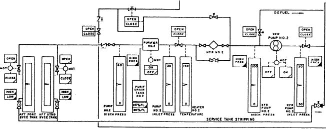
HEATER NO. 2 TEMPERATURE, monitors the
No. 2 system serves the AFT FO service system.
FO heater discharge temperature. It is scaled in
The transfer system consists of a system of pipes
degrees Fahrenheit. The sixth meter, labeled XFR
from the storage tanks to the service tanks and
PUMP NO. 2 DISCH PRESS, monitors the
the associated equipment necessary to move fuel
discharge pressure of the No. 2 FO transfer pump
between them. Each transfer system contains two
and is scaled in psig. The last meter, labeled XFR
service tanks, a FO purifier, a purifier drain tank,
PUMP NO. 2 INLET PRESS, monitors the
a FO heater, and a transfer pump. Since each
inlet pressure of the No. 2 FO transfer pump
system is identical, only the No. 2 fuel system will
and is scaled in psig. There is one split-legend
be discussed. Refer to section A of figure 9-10.
push button labeled ON and OFF. This ON/OFF
push-button indicator controls the fuel purifier
This section has five split-legend indicators
motor. This push button turns the purifier motor
labeled OPEN and CLOSE. They illuminate
off if it is on, but it cannot be used by the operator
to start the purifier motor from the FSCC. The
either OPEN or CLOSE to indicate the position
of the manually operated cross-connect valves.
ON portion of the push button is a status indicator
There are four indicator control push buttons in
that shows the purifier motor is running. This
this section. Two are labeled OPEN and two are
section has two indicator control push buttons the
operator can use to operate the FO transfer pump
labeled CLOSE. These push buttons operate the
service tank fill valves. The OPEN push button
motor. One push button is labeled OFF and the
illuminates green when the valve is fully open. The
other is labeled ON. The OFF push button
CLOSE push button illuminates white when the
illuminates white when the motor is secured. The
valve is fully closed. The three push-button alarm
ON push button illuminates green when the motor
indicators, labeled HIGH PRES, illuminate
is running. There are two split-legend alarm
indicators labeled HIGH and LOW. The HIGH
amber to indicate that the purifier discharge
pressure, the transfer pump discharge pressure,
indicator illuminates amber when the service
or the transfer pump inlet pressure has exceeded
tank level reaches 90 percent. The LOW indicator
the preset limit. The first meter in this section is
illuminates amber when the service tank level
labeled AFT PORT SVCE TANK. This meter
drops to 10 percent. The last split-legend alarm
monitors the fuel level in the AFT PORT service
indicator, labeled 80% FL and 95% FL, monitors
tank. The second meter, labeled AFT STBD
the FO level in the purifier drain tank. The 80%
SVCE TANK, monitors the FO level in the AFT
indicator illuminates steadily when the drain tank
STBD service tank. The service tank meters are
is 80 percent full. The 95% alarm indicator
scaled to indicate fuel levels in gallons. The third
illuminates amber when the level reaches
95 percent. The No. 1 FO transfer section
meter, labeled PURIF NO. 2 DISCH PRESS,
monitors the discharge pressure of the No. 2 FO
(section B of fig. 9-10) is the same as the
purifier and is scaled in psig. The fourth meter,
section we have just discussed, except this
labeled PURIF NO. 2 INLET PRESS, monitors
section contains the meters, indicators, and
the inlet pressure of the No. 2 FO purifier and
push-button controls for the No. 1 fuel transfer/
is scaled in psig. The fifth meter, labeled
service system.
9-13