
ELECTRICAL DISTRIBUTION SYSTEM
The generators each supply separate switchboards
that serve as the central control points for the PHM's
electrical distribution system. A bus tie between the
main switchboard busses allows the generators to
supply the ship's systems either individually, in the
split-plant mode, or in the parallel mode. There are two
switchboards used for power distribution: (1) the main
deck switchboard and (2) the platform deck
switchboard.
Main Deck Switchboard
The main deck switchboard (1S) is shown in figure
6-35. The main deck switchboard interfaces electrically
with the 450-V ac, 400-Hz, 3-phase power output of
generator No. 1 and shore power receptacle No. 1.
As shown in figure 6-35 the enclosure for this
Figure 6-36.--Platform deck switchboard.
switchboard is equipped with hinged doors and
removable faceplate panels. For operational access, the
circuit breakers, switches, and fuses are mounted on
Shore Power Receptacles
these panels. Internally, the switchboard contains
contractors, relays, fuses, transformers, control modules,
The two shore power receptacles, shore power
and electrical busses.
receptacles No. 1 and No. 2, are each capable of
receiving 450-V, 3-phase, 400-Hz shore power. Each
receptacle is rated for the shore power electrical load of
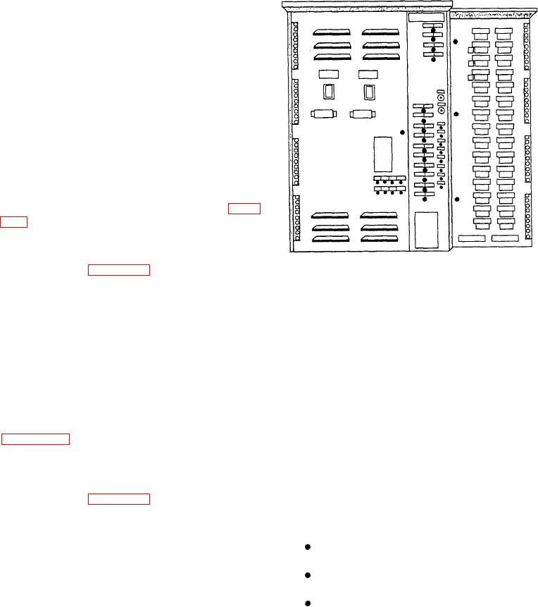
Platform Deck Switchboard
the ship, plus a 30 percent growth margin.
Each receptacle is connected to its respective ship's
The platform deck switchboard (2S) is shown in
electrical power system switchboards. Manual controls
figure 6-36. The platform deck switchboard is
for the receptacles are provided both at the EOS console
essentially the same as the main deck switchboard,
and the switchboards. Shore power monitors are
except that it serves generator No. 2 and shore power
installed in each switchboard to make certain the input
receptacle No. 2.
voltage, frequency, and phase rotation are within the
As shown in figure 6-36, the enclosure for the
following limits before shore power is applied to the
platform deck switchboard is equipped with hinged
ship's electrical system:
faceplate doors and removable front panels for
maintenance access. Circuit breakers, switches, and
410 to 471 V ac
Voltage
display meters are installed on the panel doors. The
electrical power busses, terminal strips, switching units,
365 to 435 Hz
and control modules are mounted inside the enclosure.
AB, BC, CA
Phase rotation
SHORE POWER
The shore power receptacles also provide capability
to supply 450-V, 3-phase, 400-Hz power to one or two
A means of supplying electrical power to the PHM
sister ships, although feedthrough capability is not
from an external source is known as shore power. This
provided. Instead, a portable shore power cable
installation consists of shore power receptacles, a
assembly, 30 meters in length, is provided to connect the
portable shore power cable, and a mobile electric power
shore power receptacles to the sister ship.
plant.

