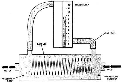
(See figure 11-2.) Baffles inside the element create
a flow restriction. As air or nitrogen enters the
element, a pressure buildup is created at the inlet
end; as it flows past the baffles, a pressure drop
occurs at the outlet end. The inlet (pressure
buildup) tap is connected to the bottom of the in-
dicating manometer, and the outlet (pressure
drop) tap is connected to the top of the
manometer. As the control valve is opened, gas
flows from the valve through the Vol-O-Flo, and
the pressure drop thus created allows the fluid in
the manometer to rise. The operator reads the
amount of flow passing through the V0l-O-Flo
on the indicating manometer.
CONTROL VALVES
A control valve regulates, or restricts, a
specified flow. Two types of control valves,
measuring and nonmeasuring, are used on the test
stand. Measuring control valves have measuring
devices (gauges or manometers) to visually
measure the flow through the valve as it is opened.
Nonmeasuring control valves have no indicating
devices. There are six measuring and three
nonmeasuring control valves on the test stand.
Measuring Control Valves
The measuring control valves (fig. 1 l-l) are
as follows:
1. The INPUT valve (A) allows a measurable
flow of air into the altitude chamber. It can only
be used during simulated altitude conditions. As
the chamber altitude increases, pressure inside the
chamber decreases, and the ambient air pressure
outside the chamber is greater. When valve (A)
is opened, air from outside the chamber flows
through valve (A); through the input Vol-O-Flo
element, indicating the amount of air flow on the
INPUT FLOW manometer (2); and through the
INPUT port (22) into the chamber.
2. The VACUUM CONTROL valve (B1) on
Model 1172AS100 allows direct evacuation of the
altitude chamber to the desired simulated altitude
by decreasing pressure in this chamber.
3. The OUTPUT valve (C), when opened,
draws a direct flow from the item under test
through the piezometer (26), OUTPUT port (23),
FLOW SELECTOR valve (M) and the output
Vol-O-Flo element to the vacuum pump. As the
flow passes through the output Vol-O-Flo, the
pressure is displayed on the OUTPUT FLOW
manometer (1).
4. The LEAKAGE CONTROL valve (E)
controls the flow to the LOW-PRESSURE
connection (19), which is located inside the
chamber. As the name of the valve implies, it is
used to perform various leak tests on oxygen
components. When you use the LEAKAGE
CONTROL valve (E) to perform leakage tests on
components, a line with bayonet fittings must
be installed between the LOW-PRESSURE
connection (19) and the REFERENCE-TAP
connection (21 ). This allows the flow passing
Figure 11-2.—VOI-O-FIO element.
11-6
239.477