in the feed dog with a distance of 17/32 inch
between the needle bar and the presser bar.
In centering the feeding action, the following
sequence should be followed: Hold the needle
centered in the feed dog with a 17/32-inchspace
between the needle bar and presser bar. Tighten
the feed driving crank and feed driving rockshaft
crank pinch screws, making sure that the crank
is flush with the end of the feed driving rockshaft
and parallel with the bed. Next, tighten the needle
bar rock frame rockshaft crank pinch screw in the
back of the uprise. The shank of the presser foot
is 17/32 inch wide and may be used for measuring
the space.
The next step is to set the sewing hook to or
from the needle. This is done by moving the hook
saddle left or right as necessary; the hook should
pass the needle as closely as possible without
touching. When this is done, retighten the hook
saddle screws. Next, set the sewing hook with the
needle. With the needle bar on the upstroke, the
lower timing mark on the needle bar should be
just visible at the base of the needle bar rock
frame. Set the point of the sewing hook in the
center of the needle 1/16 inch above the eye. To
advance the sewing hook, move the hook drive
gear to the right; and to retard, move the hook
drive gear to the left.
NOTE: The first screw in the hook pinion
gear and the second screw in the hook
drive gear are splined screws. The hook
drive gear must be centered in relation to
the sewing hook shaft at the bottom of the
hook saddle. “
Lubrication of The Class 111
Sewing Machines
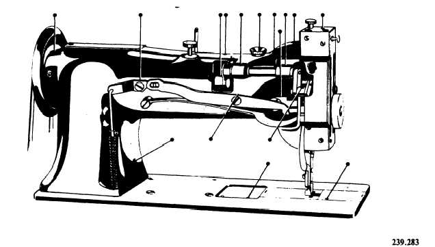
Figures 9-24A, 9-25B, and 9-26 show the
various lubrication points on class 111 sewing
machines. Oiling points are indicated by the
unnumbered arrows. Familiarization with the
nomenclature of the machines may also be
accomplished by studying these illustrations.
To lubricate the class 111 machine, swing back
the top cover and oil the bearings, then replace
the cover.
Loosen the thumbscrew in the upper end of
the faceplate, turn the faceplate upward, and oil
the wick and bearings, as shown in figure 9-25B.
After oiling, turn down the faceplate and tighten
the thumbscrew.
Turn the machine back on its hinges and apply
oil at the places designated by the arrows in figure
9-27. All contacting parts on the bottomside of
the machine should also be oiled.
To lubricate the hook, remove the bed slide
and place oil in the oil well (fig. 9-26). This
Figure 9-26.—Rear of machine, showing oiling points.
9-22