turn the screw clockwise. To decrease the tension,
turn the screw counterclockwise.
The tension on the machine and bobbin
threads should be checked by test-running a row
of stitches on scrap material. The lockstitch
should lock in the center of the material, as
described for the 31-15. When sewing webbings
with the 7-33 sewing machine, the specifications
for webbing sewing should be checked to
determine at what ply of the webbing the stitch
should lock.
Regulating the Length of Stitch
The procedure for regulating the stitch on
the 7-33 ‘sewing machine
31-15.
Regulating the Pressure
on the Material
is the same as for the
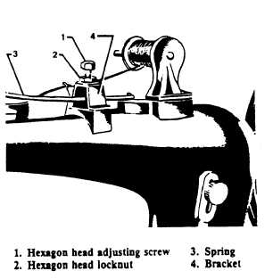
The pressure on the material is regulated by
means of the hexagon head screw (1). (See figure
9-22.) Loosen the hexagon head locknut (2) and
turn the adjusting screw clockwise to increase the
pressure, or counterclockwise to decrease the
pressure on the spring (3). When the desired
pressure has been obtained, hold the adjusting
screw with a wrench to keep it from turning while
239.279
Figure 9-22.—Regulating the pressure on the material.
9-17
the locknut is being tightened against the bracket
(4).
The pressure should be just heavy enough to
enable the feed dog to move the work along
evenly, and to prevent the work from rising with
the needle.
Preparing the Sewing
The same sewing preparatory procedures are
used for the 7-33 as for the 31-15 sewing machine,
except there is no knee lifting device. The hand
presser bar lifter is the only device provided for
lifting the presser foot on the class 7-33 sewing
machine.
Removing the Work
Stop the machine and raise the thread take-
up lever to its highest position. Draw about 3
inches of thread through the thread retaining
disks. Raise the presser foot and draw the work
back, cutting the threads close to the material.
Leave the ends of the threads under the presser
foot .
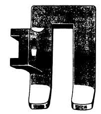
Modification of Presser
Foot for Webbing Sewing
The modification of a presser foot is illustrated
in figure 9-23. The presser foot should be cut
239.280
Figure 9-23.—Modification of presser foot for webbing
sewing.