possible, then, to obtain relative bearings of objects by
merely training the vanes on an object, then reading
the graduation on the inner circle alongside the
lubber’s line on the pelorus or repeater.
Each of the far vanes contains a spirit level to
indicate when the circle is level. Bearings taken when
the azimuth or bearing circle is not on an even keel are
inaccurate.
TELESCOPIC ALIDADES
Another means of taking bearings is by using an
alidade, which, like the bearing circle, is mounted on
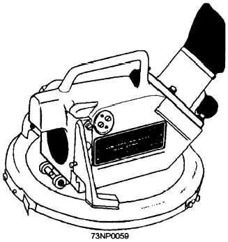
a repeater. The telescopic alidade (fig. 9-3) is merely
a bearing circle with a small telescope attached to it.
The image is magnified, making distant objects appear
larger to the observer. A series of prisms inside the
low-power telescope enables the bearing-taker to read
the bearing directly from the compass card without
removing the eye from the eyepiece.
Bearings and azimuths may be true, per
gyrocompass (PGC), magnetic, or per steering
compass (PSTCO). When you are helping the
navigator in piloting, you probably will report
bearings directly from the gyro repeater, and the
navigator will correct them to true.
Figure 9-3.—Telescopic alidade.
CHARTS AND PUBLICATIONS
LEARNING OBJECTIVES: Explain the use of
navigational charts and publications. Explain
chart scales, chart sounding marks, and how to
make chart corrections.
A map represents pictorially all or part of Earth's
surface. Maps specially designed for navigators are
called charts. Navigational charts show water depths
and the nature of the bottom, together with a
topography of adjacent land.
A chart is a printed reproduction of a portion of
Earth's surface depicting a plan view of the land and
water. A chart uses standard symbols, figures, and
abbreviations that supply data on water depth,
characteristics of the bottom and shore, location of
navigational aids, and other information useful in
navigation. Figures indicating water depth are placed
throughout the water area to indicate the shape of the
bottom. Normally the density of sounding on a chart
increases as you approach land. A chart is normally lined
with a network of parallels of latitude and meridians of
longitude, which aid in locating various features.
LOCATING POSITIONS ON CHARTS
Earth is approximately an oblate (flattened at the
poles) spheroid. However, for most navigational
purposes, Earth is assumed to be a sphere, with the
North Pole and South Pole located at opposite ends of
the axis on which it rotates. To establish a feature's
location geographically, it is necessary to use two
reference lines, one running in a north-south direction
and the other in a east-west direction. Numerical
designators are applied to these reference lines. The
numerical system used is circular and consists of 360°,
with 60 minutes or 3,600 seconds in a degree.
Lines running in the north-south direction, called
meridians, start at one pole and end at the opposite
pole. (See fig. 9-4.) Lines running east-west are
parallel lines and are called parallels.
Meridians
The prime (0°) meridian, which is the reference
line for all meridians, passes through the Royal
Observatory located at Greenwich, England. Earth is
divided into Eastern and Western Hemispheres. All
meridians are numbered between 0° and 180° east and
west of the prime meridian. In addition to the number
value, each line is identified by the letter E or W,
denoting the proper hemisphere.
9-3