CABLE ANCHOR DAMPER
LEARNING OBJECTIVE: Describe the
components of the cable anchor damper.
The cable anchor damper installation consists of
two identical anchor damper assemblies. In most cases
one cable anchor damper assembly is deck mounted
and the second assembly is overhead mounted (fig.
3-20). Compartment configuration determines how the
units are installed.
The purpose of the cable anchor damper is to
eliminate excessive purchase cable slack between the
crosshead and fixed sheave assembly at the beginning
of the arrestment stroke. Through service use and
experimental testing, it was found that when this cable
slack was taken up by the landing aircraft, excessive
vibrations occurred in the engines. The cable anchor
damper removes this slack as it occurs, thereby
eliminating vibration of the purchase cable. The cable
anchor damper assembly is used with pendant engines
only.
Referring to figure 3-20, note that each cable
anchor damper assembly includes a cylinder that
connects to an operating end head and a cushioning end
head. Piping connects the engine cylinder to the
operating end head through a manifold tee. Two lines
branch from the manifold tee, one to each damper
assembly operating head. Each of these lines contains a
flow control valve. A cover is placed over the operating
piston rod and coupling assembly for safety of
operation and protection against foreign matter. Each
damper assembly is mounted on a base before
installation.
A battery positioner, actuated by the retracting
lever, is provided to ensure the return of the damper
assembly
to
the
BATTERY
position
after
an
arrestment. A battery-position indicator is provided to
indicate when the cable anchor damper is in the
BATTERY position, ready for aircraft engagement.
The
limit
switch
and
cam
actuator
for
the
battery-position indicator are located on the cable
anchor damper assembly, and the indicator lights are
located on the arresting engine control panel.
The end of the purchase cable is attached to the
operating end piston rod by an anchor damper coupling.
When the force on the operating piston, due to engine
cylinder pressure, is greater than the tensile force in the
purchase cable, the piston moves away from its
BATTERY position. Movement of the operating piston
into the cylinder removes the cable slack during the first
portion of the arrestment. When the slack is taken up,
the operating piston resists the return of the cable, thus
keeping
it
taut
and
preventing
excessive
cable
vibration.
3-21
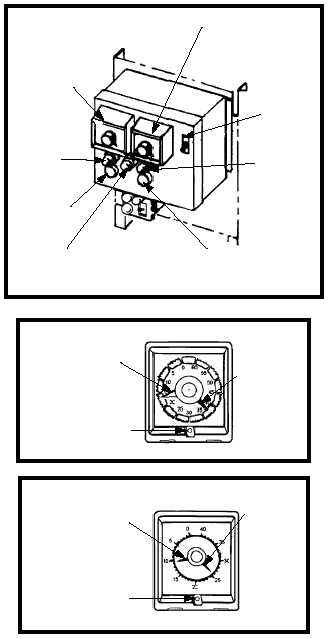
MONITOR
TIMER
(DETAIL A)
COUNTER
(DETAIL B)
ON/OFF
SWITCH
FAULT
(RED)
MANUAL RUN
READY
(GREEN)
RESET
LUBE
(AMBER)
LUBRICANT CONTROLLER
RED CYCLE PROGRESS POINTER
REGISTERS COUNTS
REMAINING TRAVELS TO
"0" DURING COUNT
ORANGE CYCLE PROGRESS
POINTER REGISTERS TIME
REMAINING TRAVELS TO
"0" DURING COUNT
LOCKING
SCREW
LOCKING SCREW
BLACK TIME SET
POINTER HAS
FULL SCALE
ADJUSTABILITY
THROUGH 320o
BLACK SET
POINTER HAS
FULL SCALE
ADJUSTABILITY
THROUGH 320o
DETAIL A
DETAIL B
ABEf0319
Figure 3-19.—Automatic lubrication controller.