Upon engagement of the deck pendant by the
aircraft, the engine crosshead is accelerated toward the
fixed sheaves. This movement forces the ram into the
arresting engine cylinder, increasing the fluid pressure
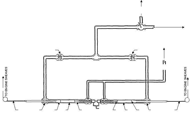
in both the engine cylinder and the operating head of
each cable anchor damper. See figure 3-21.
Because of the acceleration rate of the engine
crosshead, the tension in the purchase cable (2)
between the engine sheaves and the cable anchor
dampers decreases momentarily. The instant the tensile
force in the cable becomes less than the force on the
operating piston (4), fluid pressure moves the operating
piston away from its BATTERY position until all slack
is removed and the cable tension is again greater than
the fluid pressure force acting on the operating piston.
The flow control valve is a clapper-type check
valve that allows free flow of the fluid one way and a
restricted flow in the opposite direction. The engine
fluid has free flow through the flow control valve (1) to
the operating end of each cable anchor damper. When
the tension of the purchase cable is transmitted to the
cable anchor ends, the fluid pressure on the operating
pistons is overcome by this cable tension, and the
operating pistons are pulled back toward BATTERY
position. Resistance to their return is furnished by the
engine fluid pressure and the controlled flow of fluid
through the flow control valves back to the engine
cylinder.
CUSHIONING PISTON
The sole function of the cushioning piston is to
prevent the operating piston from slamming into the
opposite end of the cable anchor damper assembly if
the purchase cable should break or in the event of an
extreme off-center landing. In either situation, the
operating piston accelerates away from its BATTERY
position and rams the cushioning piston.
3-23
TO ARRESTING ENGINE
HYDRAULIC CYLINDER
TO ACCUMULATOR
HYDRAULIC SYSTEM
2
3
4
5
6
6
5
4
1
1
RETRACTING VALVE
TO ACCUMULATOR
HYDRAULIC SYSTEM
3
2
TO 3-WAY
AIR VALVE
1. FLOW CONTROL VALVE
2. PURCHASE CABLE
3. OPERATING HEAD
4. OPERATING PISTON
5. CYLINDER
6. CUSHIONING PISTON
ABEf0321
Figure 3-21.—Cable anchor damper fluid flow (arrestment).