A4.
The maximum rotation of the A/F 32K-1/1A
bomb assembly stand is 360 degrees.
A5.
The Aero 64A1 hoisting bar is used to
manually lift Sparrow missiles.
A6.
When using two Aero 68A hoisting bars,
1,000 pounds is the maximum weight that can
be lifted.
A7.
The HLU-256/E hoisting bar is used to
manually lift Mk 82 bombs.
ADU-399/E GUIDED MISSILE HOISTING
BEAM
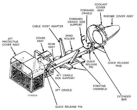
The ADU-399/E guided missile hoisting beam (fig.
9-16) is an aluminum weldment that consists of a beam
supported on forklift channels and structural members.
These
components
form
the
base
assembly.
Rubber-lined cradles mounted fore and aft on the beam
prevent metal-to-metal contact. The cradles have side
supports held in position by quick-release pins. When
you are loading or unloading the beam, remove the
quick-release pins to let the side supports swing down
out of the way. There are two adjustable tubular
extenders on the fore end of the beam that support a
vinyl-covered housing. The housing protects the
weapon's radome. Quick-release pins secure the
extenders to the beam and the radome protector to the
extenders. There are cable hoists mounted on the base
assembly and held in the hoisting position by
quick-release pins. When the pins are removed, the
hoists swing down and forward into the stowed
position.
The ADU-399/E guided missile hoisting beam is
used for ground support handling of the Phoenix
missile during aircraft loading/unloading operations.
This beam may be used in conjunction with the
HLU-196B/E bomb hoist, the A/M32K-1A/1B/1C
SATS loader, or the ADU-400/E weapon skid loading
adapter.
MHU-129/E GUIDED MISSILE HOISTING
BEAM
The MHU-129/E guided missile hoisting beam
(fig. 9-17) is aluminum I-beam with a lifting eye
mounted on the top of two removable lifting-shoe
assemblies. The shoe assemblies are secured to the
lower flange of the beam with quick-release pins
designed to engage the forward and aft launch lugs of
the Phoenix guided missile. The safety latches in the
shoe assemblies secure the beam to the missile.
9-10
Figure 9-16.—ADU-399/E guided missile hoisting beam.