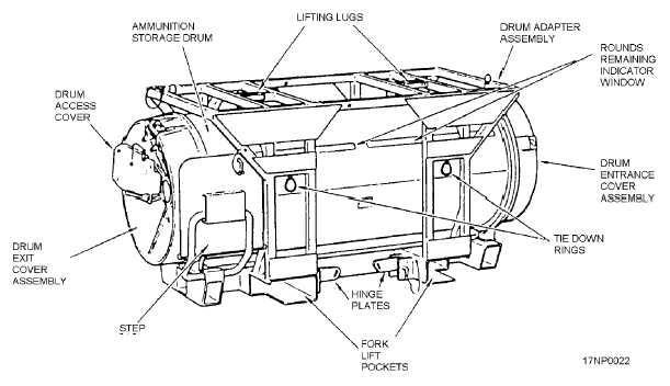
The drum adapter assembly is a box-type structure
that allows the transporters to be stacked. Four hinge
plates and four quick-release pins are used to lock the
transporter onto the MHU-191/M transporter. Two
lifting lugs (on 30-inch centers) mate with a weapons
carrier so that an overhead crane can be used to lift the
transporter. Additionally, there are two forklift pockets
that allow the forklift truck to move the transporter.
There are four tie-down rings to secure the transporter
to the deck. Foldout steps, if needed, are located at the
exit end of the transporter to provide personnel with the
additional height to operate the LALS.
The ammunition drum is a cylindrical structure that
consists of an outer drum structure, an inner drum, two
scoop disk assemblies, and two cover assemblies.
OUTER DRUM.—The outer drum is a storage
container for ammunition, and it provides a housing for
the inner drum. There is a rounds-remaining indicator
window so you can determine the number of rounds
remaining in the drum. The drum partitions, mounted
longitudinally within the outer drum to hold the rounds
in place, hold the rounds radially around the outer drum
with their bases in an outward direction.
INNER DRUM.—The inner drum is a welded
assembly with a mounting ring at each end. There are
sheet metal leaves welded to the outer surface of the
core that form a double-lead helix. When the inner
drum is rotated, it moves the rounds along the drum
partitions from the entrance end to the exit end of the
drum.
SCOOP DISK ASSEMBLIES.—A scoop disk
assembly is mounted on each end of the inner drum.
There are three rails on the scoop disk assemblies,
forming a continuation of the inner drum helix. Also,
two sets of gear-driven sprockets and scoop extensions
are located on the scoop disks 180 degrees apart. These
sprockets and scoop extensions transfer the rounds
from the entrance cover to the outer drum partitions and
from the outer drum partitions to the exit cover. The
entrance scoop disk has two pins that hold the scoop
extensions closed when they are activated by a cam in
the outer drum. This prevents feeding rounds into the
empty space where the drum partitions cannot control
the rounds.
DRUM COVER ASSEMBLIES.—A drum cover
assembly is mounted on each end of the outer drum.
The drum cover assemblies accept rounds from the
entrance unit, load units, or from the scoop disk
assembly. It then places the rounds into the scoop disk
assembly (entrance end) or exit unit, respectively. The
retainer partitions on the retainer gear maintain control
of the rounds between the scoop disk assemblies and
the entrance or exit units. A spring-loaded timing pin on
each drum cover is used to index the drum during
installation of the entrance and exit units. The exit drum
cover assembly also contains brackets for mounting a
drive assembly.
7-11
Figure 7-13.—Transporter.