forward missile-mounting button. The external rail
flanges are a guide for the aft missile suspension lugs
during firing. The aft section of the rail consists of a
removable fitting that provides mounting for the aft
missile suspension lugs.
REVIEW NUMBER 6 ANSWERS
A1.
The LAU-7/A missile launcher is used to
carry and launch the Sidewinder missile.
A2.
The four major assemblies of the LAU-7/A
launcher
include
the
housing,
nitrogen
receiver, mechanism, and power supply as-
semblies.
A3.
The nitrogen receiver assembly is used to
store high-pressure nitrogen (3,200 psig) that
is used to cool missile IR detector guidance
systems.
A4.
The detent, detent lock, detent-lock solenoid,
and snubber subassemblies of the mechanism
assembly are an electromechanical system
that
restricts
longitudinal
and
lateral
movement of mounted missiles. This prevents
accidental launch or release during catapult
takeoffs or arrested landings.
A5.
The
LAU-7/A
guided
missile
launcher
provides a complete system that lets the pilot
monitor the condition of the missile during
flight, control mode of operation of the
missile guidance system, and initiate arming
and launch sequence.
The latch mechanism is composed of a detent cam
and keeper. The detent cam is spring-loaded down and
acts as a stop during missile loading. The cam
mechanism is constructed so the force created by the
missile motor during normal missile firing overcomes
the detent cam spring tension. This action lets the
missile button push the detent cam up, actuating the
missile-gone switch.
An electrically operated solenoid is used to assure
that the missile is retained during sudden deceleration,
such as an arrested landing. The keeper portion of the
latch mechanism is spring-loaded to the down position
and retains the missile during all periods of aircraft
acceleration. The keeper mechanism has an indicator.
When the keeper is in the down or latched position, the
indicator is flush with the launcher skin. If, during
missile loading, the missile button is not in its
maximum forward position, the indicator extends
beyond the upper launcher mold line. This indicates
that the missile is not properly latched in place. During
loading, the missile button can slide past the keeper,
stopping when contact is made with the detent cam.
During the unloading of a missile, the indicator bell
crank is supported in the launcher structure. Using a
3/8-inch square drive tool manually operates it. The
square drive end of the bell crank is accessible from the
side of the launcher. The launchers are suspended from
BRU-32 bomb racks in the outboard pylons. Two
LAU-7/A launchers can be attached for suspension of
the
AIM-9
missiles.
For
ground
safety,
an
actuator-operated safety device prevents inadvertent
loss of the AIM-7 missile.
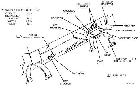
LAU-116/A GUIDED MISSILE LAUNCHER
The LAU-116/A guided missile launcher (fig.
3-22) is a reusable launcher of the F/A-18 aircraft
3-25
Figure 3-22.—LAU-116/A guided missile launcher.