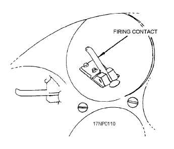
the detent. A spring-loaded firing contact (fig. 2-20) is
located in the end of each tube.
The principles of operation for the 2.75-inch
launcher are basically the same as the 5.0-inch
launcher. The 2.75-inch launcher can be loaded with
less than 7 or 19 rockets when tactical requirements
exist. However, you should refer to the specific tactical
manual and aircraft-loading manual. Also, since the
rockets are fired in a definite sequence, the rockets must
be loaded into the launcher tubes in the proper
sequence.
Airborne
rocket
loading
procedures,
including electrical test procedures, are covered later in
this manual.
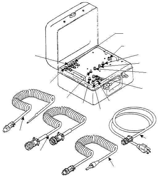
MK III ROCKET LAUNCHER TESTER
Perform the self-test of the Mk III Rocket Launcher
Tester (fig. 2-21) prior to loading launchers in
accordance with NAVAIR 17-15MDA-40.
2-19
Figure 2-20.—Launcher firing contact assembly (2.75-inch
launcher).
J3
POWER CABLE
RECEPTACLE
J2
SELF-TEST
AND
TESTING
J4
SELF-TEST
AND TESTING
BINDING POSTS
FIRE TEST SWITCH
FIRE TEST INDICATOR
GROUND TEST
INDICATOR
BATTERY CHECK
INDICATOR
J1
SELF-TEST
FUZE
(BATTERY
CHARGINH)
GROUND
TEST
SWITCH
BATTERY
CHECK
SWITCH
POWER CABLE
W1
COILED CABLE
W3
COILED CABLE
W2
COILED CABLE
W4
AOf0221
Figure 2-21.—Mk III Rocket Launcher Tester with cables.