
The most common 5-micron filter medium is
composed of organic and inorganic fibers integrally
bonded by epoxy resin and faced with a metallic mesh
upstream and downstream for protection and added
mechanical strength. Filters of this type are not to be
cleaned under any circumstances, and will be marked
DISPOSABLE or NONCLEANABLE, usually on the
bottom end cap.
Five-micron, noncleanable, hydraulic filter
elements should be replaced with new elements during
s p e c i fi e d m a i n t e n a n c e i n s p e c t i o n i n t e r va l s i n
accordance with the applicable procedures. Refer to
the applicable MIM or maintenance requirement cards
(MRC) for replacement intervals and procedures.
Another 5-micron filter medium of recent design
employs layers of very fine stainless steel fibers drawn
into a random but controlled matrix. The matrix is then
processed by an exclusive procedure, which in
successive steps compresses and sinters (bonds all
wires at their crossing points) the material into a thin
layer with controlled filtration characteristics. Filter
elements of this material may be cleanable or
noncleanable, depending upon their construction, and
are marked accordingly.
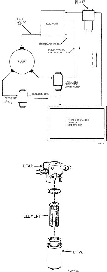
Figure 12-31.--Typical filter arrangement in hydraulic system.
Support Equipment (SE) Filters
To ensure delivery of contaminant-free hydraulic
fluid, all SE must be provided with 3-micron (absolute)
non-bypass filtration in their fluid discharge or output
pressure lines. With many test stands, the filter used
for this application, in addition to having a low micron
rating, must be capable of withstanding high-collapse
pressures and holding large amounts of dirt.
Unlike most filter elements, 3-micron,
high-pressure SE filters are not normally replaced on a
prescribed periodic basis. Because of their large
dirt-holding capacity and nature of service, it is more
effective to replace such elements only when indicated
as being loaded by their associated differential
pressure indicators. Element replacement procedures
va r y w i t h t h e p a r t i c u l a r t y p e , a n d a p p l i c a b l e
maintenance instructions should be consulted for
specific procedures.
Figure 12-32.--Hydraulic filter assembly.
Differential Pressure Indicators
hydraulic system at much cleaner levels than could
The extent to which a filter element is loaded can
previously be achieved. The use of 5-micron
be determined by measuring the drop in hydraulic
(absolute) filters is presently specified for all new
p r e s s u r e a c r o s s t h e e l e m e n t u n d e r r a t e d f l ow
design aircraft, and they are being retrofitted to
conditions. This drop or "differential pressure"
existing fleet aircraft where practicable.
provides a convenient means of monitoring the
12-31

