
3. Tighten the nuts on the attaching bolts
Q15-9. Aircraft with a type II hook assembly installed
fingertight. Safety with cotter pins.
requires an inspection of the arresting hook
stinger and centering block after how many
4. Torque the rod end jam nuts to 270-300
recorded arrestments?
inch-pounds and safety with lockwire, as shown in
figure 15-8.
Q15-10. What centering device prevents side move-
ment of the arresting gear mechanism during
5. Check lateral movement of the hook in
carrier-arrested approaches?
accordance with the procedures prescribed in the MIM.
Q15-11. What prevents arresting hook motion caused
Intermediate-level maintenance of the centering
by deck impact forces?
springs consists of checking the disassembled parts for
scoring, corrosion, nicks, structural deformation, or
Q15-12. Disassembly and assembly of the arresting
failure. Nonferrous parts are subjected to fluorescent
gear centering spring require extreme
penetrant inspection and ferrous parts to magnetic
caution due to spring forces in excess of how
particle inspection. The diameter of all parts and the
many pounds?
free length dimensions of the two springs, shown in
figure 15-8, are checked against the values given in the
CATAPULT LAUNCH SYSTEM
parts tolerance tables provided in the MIM.
LEARNING OBJECTIVE: Identify the
types of catapult launch systems. Identify their
components and applicable maintenance re-
WARNING
quirements.
Disassembly and assembly require extreme
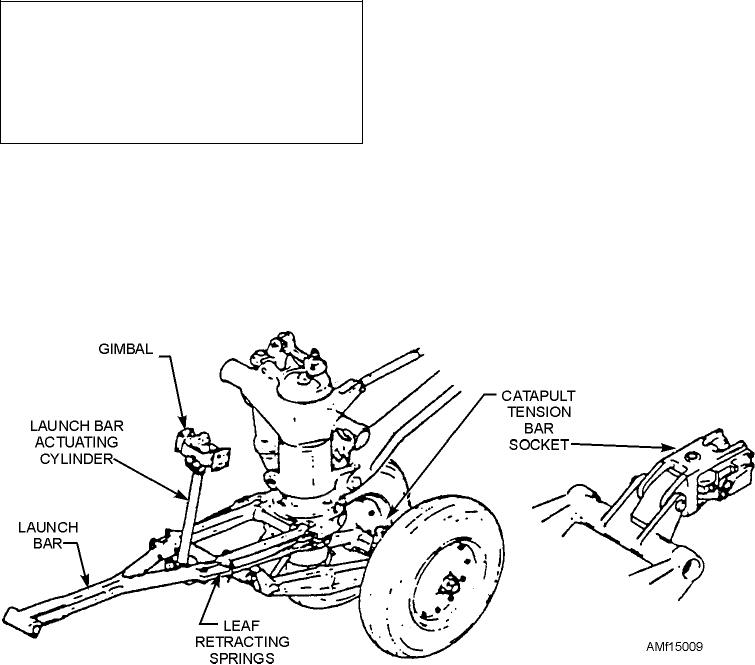
The purpose of the nose landing gear catapult
caution. The spring force is in excess of 500 pounds.
launch system is to provide a means of directing the
Failure to observe the proper safety precautions could
aircraft into position for catapult launching, as well as
result in personnel injury.
being connected automatically to the ship's catapult
equipment. Such a device eliminates the necessity for
Post repair testing includes checking the breakout
flight deck personnel to manually connect catapult
force required to extend and compress the springs.
harnesses. The system consists of a catapult launch bar,
Force required is 560 60 pounds. The spring should
a launch bar actuating cylinder and gimbal, selector
extend 1.60 inches 0.03 inch and compress 1.40
valve, leaf retracting springs, and a catapult tension bar
inches 0.03 inch from neutral.
socket. See figure 15-9.
Q15-8. How many different types of arresting hooks
The launch bar is swivel mounted on the forward
are currently used on naval aircraft?
side of the nose gear outer cylinder and may be
Figure 15-9.--Catapult system.
15-10

