
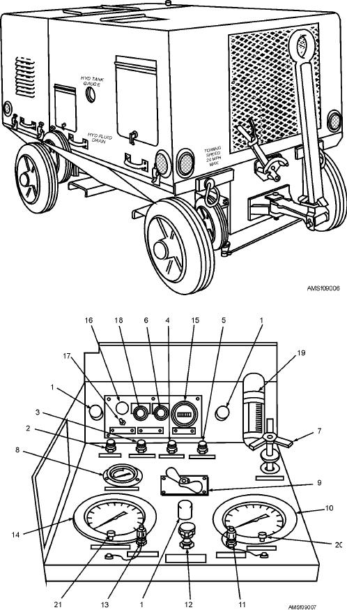
Figure 9-6.--Portable electric motor-driven hydraulic power supply (A/M27T-7).
16. Power on indicator light
11. L.P. gauge teat fitting
6. Stop push-button switch
1. Panel lights
17. Off-master-on switch
12. Pressure bypass valve
2. High-pressure filter indicator light 7. Compensator control
18. Start push-button switch
13. H.P. gauge test fitting
8. Fluid temperature gauge
3. Pump case filter indicator light
19. Pressure outlet flow meter
14. High-pressure gauge
4. Low-pressure filter indicator light 9. Selector valve
20. Compound gauge calibration screw
15. Hour meter
10. Compound gauge
5. Fluid temperature warning light
21. High-pressure gauge calibration screw
Figure 9-7.--Primary control panel controls and indicators.
9-10

